
Supercapacitor having electrode material comprising single-wall carbon nanotubes and process for making the same

a carbon nanotube and supercapacitor technology, applied in the direction of electrolytic capacitors, multiple hybrid/edl capacitors, nano-informatics, etc., can solve the problems of low energy storage capacity, limited power density and the number of charging cycles, and suitable metal oxides

Inactive Publication Date: 2006-06-13
GEORGIA TECH RES CORP
View PDF9 Cites 242 Cited by
  • Summary
  • Abstract
  • Description
  • Claims
  • Application Information

AI Technical Summary

Benefits of technology

The present invention is about a new type of capacitor that uses a special type of carbon called single-wall carbon nanotubes and polymer. The electrodes are made by mixing polymer and nanotubes and then heating them to create a carbon material that can be used in a supercapacitor. The resulting material has high surface area and is able to store energy and release it quickly. The invention also includes a method for making the electrodes and a supercapacitor design. The technical effects of this invention include improved energy storage and higher power density compared to traditional capacitors.

Problems solved by technology

Although batteries have the potential for high energy density and can provide power over a wide range of voltages, their power density and the number of charging cycles are on-going limitations.
Although capacitors have much higher energy transfer rates than batteries and can withstand orders of magnitude more charging cycles, they are limited by their low energy storage capacity, which is commonly on the order of microfarads or picofarads.
However, due to the high cost, scarcity and toxicity of suitable metal oxides, supercapacitors based on carbon electrode materials may be preferred in many applications, especially those for power-related systems requiring higher capacitance capabilities.
One of the problems encountered with the use of different forms of activated carbon in electrodes is the lack of self-adhesion.
In addition, the use of binder materials can fill or block the pores of the activated carbonaceous material and thereby reducing the available surface area available for double layer formation.
Although the power density of supercapacitors is about ten times that of the secondary batteries, the energy density is smaller than that of secondary cells, and a serious deficiency for practical applications.

Method used


Image

  • Supercapacitor having electrode material comprising single-wall carbon nanotubes and process for making the same
  • Supercapacitor having electrode material comprising single-wall carbon nanotubes and process for making the same
  • Supercapacitor having electrode material comprising single-wall carbon nanotubes and process for making the same

Examples


example 1

[0095]This example demonstrates a method for preparing a composite film comprising single-wall carbon nanotubes and 90 / 10 poly(acrylonitrile / methyl acrylate) copolymer “P(AN / MA).” The composite is designated SWNT-P(AN / MA).

[0096]75 mg powdered 90 / 10 poly(acrylonitrile / methyl acrylate) copolymer, Mol. Wt.≈100,000 g / mol, (obtained from Aldrich) was added to 50 mls dimethylformamide (DMF) and stirred with a magnetic stirrer at room temperature for 24 hours to form a homogeneous P(AN / MA) / DMF solution. Single-wall carbon nanotubes (Lot No. HIPCO86) were obtained from Rice University, where they were made in a high temperature, high pressure, all-gas phase process through the disproportionation of carbon monoxide (CO) to SWNT and CO2 using iron as the transition metal catalyst. A suspension of SWNT was prepared by adding 50 mg unpurified, as-produced SWNT to the P(AN / MA) / DMF solution and homogenizing with a Bio-Homogenizer (Model 133 / 1281-0, Biospec Products Inc., Bartlesville, Okla.) for ...

example 2

[0097]This example demonstrates the heat treatment of SWNT-P(AN / MA) composite film samples. SWNT-P(AN / MA) composite film samples in the shape of 11.82-mm diameter round pieces were subjected to various heat treatments in the presence of different gaseous environments. Each heat treatment was conducted by placing the SWNT-P(AN / MA) composite film sample in a tubular furnace heated to a particular temperature and holding the sample at that temperature for a period of time in the presence of a particular gaseous environment. One sample, designated as a control film, was not subjected to any post-treatment in order to determine the effect of the treatments. The samples and heat treatments are listed in Table I.

[0098]

TABLE IHeat-treatmentHeatTemperaturetreatment timeHeat treatmentSample Designation(° C.)(minutes)environmentSWNT-P(AN / MA)No heatNoneNot applicableControl filmtreatmentAir-25025010airAr-4004003argonAr-7007003argonAr-270030argonAr-10001000 3argon

example 3

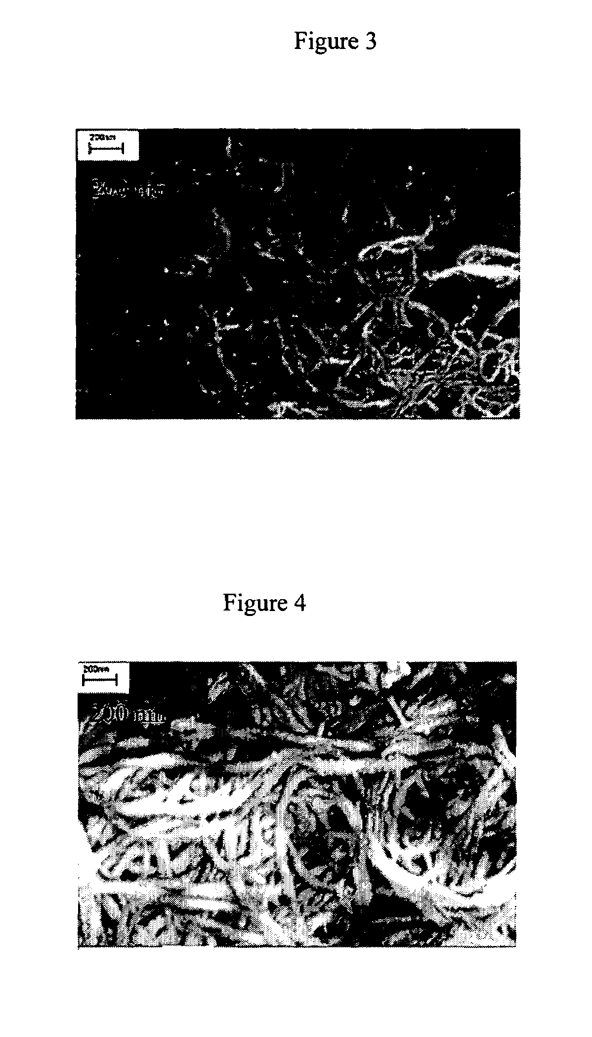
[0099]This example shows the microstructure of the heat-treated SWNT-P(AN / MA) film sample. Scanning electron micrographs (SEM) were taken of as-received single-wall carbon nanotubes (Rice University Lot HIPCO86) and the heat treated SWNT-P(AN / MA) films prepared in Example 2. FIG. 3 shows a SEM photomicrograph of the as-received single-wall carbon nanotubes. In this micrograph, the single-wall carbon nanotubes appear as a mat of tangled bundles of substantially-aligned SWNT called ropes. The diameters of the SWNT ropes in this example ranged from about 28 nm to about 42 nm.

[0100]A SEM micrograph of the SWNT-P(AN / MA) film sample heated at 700° C. for 3 minutes in argon (designated Ar-700), given in FIG. 4, shows a mat of tangled SWNT rope-like structures, similar to the as-received SWNT, but, in this case, encapsulated in P(AN / MA). The diameters of the SWNT-P(AN / MA) composite ropes in this example ranged from about 49 nm to about 65 nm. SEMs of the other heat-treated SWNT-P(AN / MA) com...


PUM

PropertyMeasurementUnit
weight ratioaaaaaaaaaa
voltageaaaaaaaaaa
temperatureaaaaaaaaaa

Abstract

The present invention relates to a supercapacitor, also known as an electrical double-layer capacitor or ultracapacitor, having electrode material comprising single-wall carbon nanotubes. The carbon nanotubes can be derivatized with functional groups. The electrode material is made by preparing a polymer-nanotube suspension comprising polymer and nanotubes, forming the polymer-nanotube suspension into a polymer-nanotube composite of the desired form, carbonizing the polymer-nanotube composite to form a carbonaceous polymer-nanotube material, and activating the material. The supercapacitor includes electrode material comprising activated carbonaceous polymer-nanotube material in contact with current collectors and permeated with an electrolyte, which may be either fluid or solid. In the case of a fluid or compressible electrolyte, an electrolyte-permeable separator or spacer is interposed between the electrodes to keep the electrodes from shorting. The supercapacitor made with electrodes comprising underivatized single-wall carbon nanotubes and polymer that has been carbonized and activated appears to operate as a non-Faradaic supercapacitor.

Description

CROSS-REFERENCE TO RELATED APPLICATION[0001]This application claims priority from U.S. provisional application Ser. No. 60 / 393,270, filed Jul. 1, 2002, which application is incorporated herein by reference.[0002]This invention was made with United States Government support under Grant No. F49620-00-1-0147 awarded by the Air Force Office of Scientific Research and under Grant No. N00014-01-1-0657 awarded by the Office of Naval Research. Government may have certain rights in the invention.FIELD OF THE INVENTION[0003]This invention relates generally to an energy storage device, more particularly to a capacitor, and even more particularly to a supercapacitor utilizing an electrode material comprising single-wall carbon nanotubes.BACKGROUND OF THE INVENTION[0004]Supercapacitors, like batteries and conventional capacitors, are types of energy storage devices. The performance characteristics of an energy storage device (ESD) can be evaluated in terms of its energy density, the amount of en...

Claims


Application Information

Patent Timeline
Patent Type & Authority Patents(United States)
IPC IPC(8): H01G9/00
CPCB82Y10/00H01G9/038H01G9/058H01G11/36H01G11/12H01G11/56H01G9/155Y02E60/13H01G11/34H01G11/38H01G11/22
Inventor LIU, TAOKUMAR, SATISH
Owner GEORGIA TECH RES CORP
Learn More