Double-clad fiber lasers and amplifiers having long-period fiber gratings

a technology of optical fiber and amplifier, which is applied in the field of optical fiber lasers and optical fiber amplifiers, can solve the problems of better noise figure, and achieve the effects of improving noise figure, uniform pumping, and increasing coupling

Active Publication Date: 2006-06-20
THE BOARD OF TRUSTEES OF THE LELAND STANFORD JUNIOR UNIV
View PDF11 Cites 16 Cited by
  • Summary
  • Abstract
  • Description
  • Claims
  • Application Information

AI Technical Summary

Benefits of technology

[0023]Aspects of systems in accordance with the present invention may also allow the rate at which light is coupled into the core of an optical fiber to be controlled. This approach has beneficial applications in rare-earth-doped fiber devices. In particular, in erbium-doped fiber amplifiers, for example, the grating may produce a more uniform population inversion along the fiber length, e.g., by increasing the coupling farther down the optical fiber. This exemplary approach may result in a better noise figure as substantially uniform pumping can be produced over the length of the fiber

Problems solved by technology

This exemplary approach may result in a better noise figure as substa

Method used


Image

  • Double-clad fiber lasers and amplifiers having long-period fiber gratings
  • Double-clad fiber lasers and amplifiers having long-period fiber gratings
  • Double-clad fiber lasers and amplifiers having long-period fiber gratings

Examples


Embodiment Construction

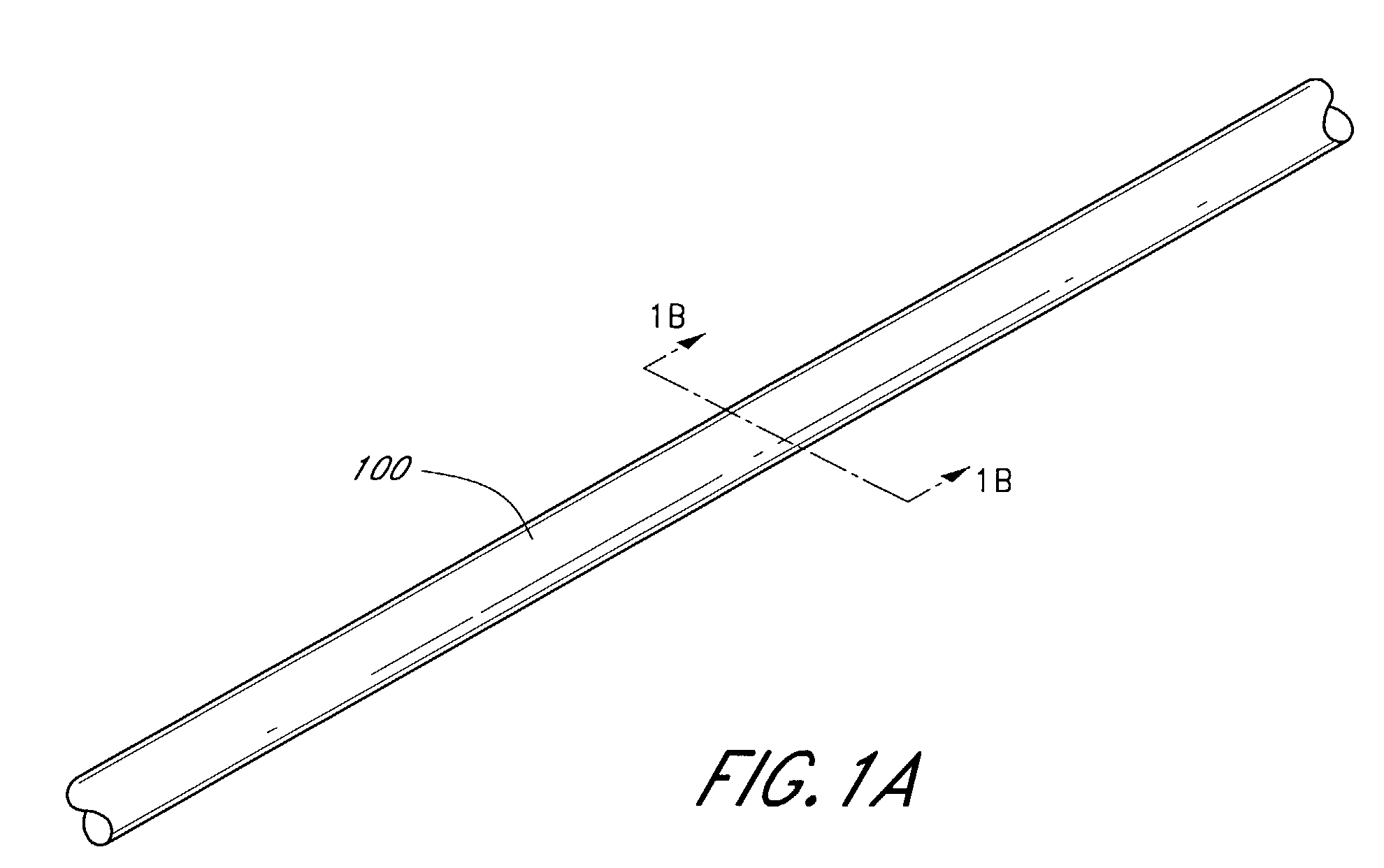
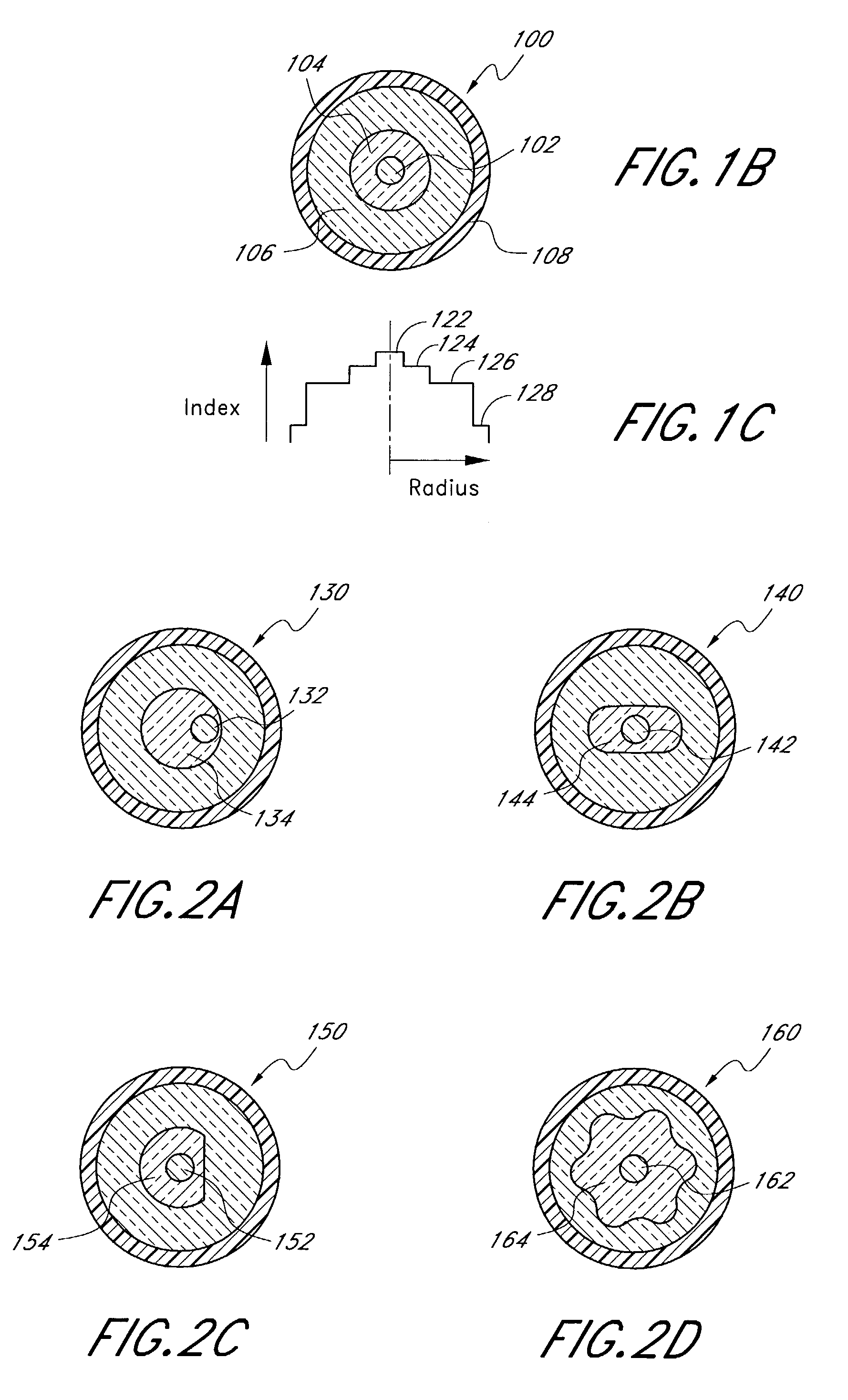
[0060]An exemplary double-clad fiber 100 is illustrated in perspective in FIG. 1A and in cross section in FIG. 1B. The double-clad fiber 100 comprises a single-mode core 102 having a generally circular cross section or other shapes, such as, for example, elliptical to produce a polarization-maintaining fiber. The core 102 is surrounded by a first (or inner) cladding 104, which also has a generally circular cross section. The core 102 is substantially centered within the inner cladding 104. The inner cladding 104 is surrounded by a second (or outer) cladding 106, which also has a generally circular cross section. The inner cladding 104 is centered within the outer cladding 106. The outer cladding 106 is surrounded by one or more protective coatings (e.g., a protective jacket) 108.

[0061]As illustrated by an index profile in FIG. 1C, the core 102 has a first refractive index 122. The inner cladding 104 has a second refractive index 124, which is lower than the first refractive index 12...


PUM


Abstract

Long-period fiber gratings are placed in a predetermined pattern along a double-clad optical fiber having an outer cladding, an inner cladding and a core. The core is doped with an optically active material such as, for example, a rare earth ion or other laser ion. The long-period fiber gratings couple light between a mode of the inner cladding and a mode of the core. As a consequence of increased coupling into the core resulting from the use of long-period fiber gratings, the length of double-clad optical fiber needed to transfer light between the inner cladding and the core is reduced.

Description

RELATED APPLICATIONS[0001]This application claims the benefit of priority under 35 U.S.C. § 119(e) from U.S. Provisional Patent Application No. 60 / 381,729, filed on May 17, 2002, and from U.S. Provisional Patent Application No. 60 / 384,146, filed on May 29, 2002, which are incorporated by reference herein.BACKGROUND OF THE INVENTION[0002]1. Field of the Invention[0003]The present invention is in the field of optical fiber systems, and, more particularly, is in the field of optical fiber lasers and optical fiber amplifiers.[0004]2. Description of the Related Art[0005]Silica-based fibers are excellent media for high-power lasers for two basic reasons. Silica-based fibers exhibit an extremely high optical damage threshold. Silica-based fibers have a high surface-to-volume ratio, which makes heat dissipation very effective. However, in a conventional fiber laser pumped with a laser diode, the pump light is coupled into the fiber core, which imposes a major limitation on the maximum pump ...

Claims


Application Information

Patent Timeline
IPC IPC(8): H01S3/00G02B6/02G02B6/036G02B6/28G02B6/42H01S3/067H01S3/094
CPCG02B6/03638H01S3/06708H01S3/0675H01S3/094003G02B6/02071G02B6/02095G02B6/0281G02B6/2852H01S3/094019H01S3/06729H01S3/094007G02B6/4214H01S5/2036
Inventor DIGONNET, MICHEL J. F.DANGUI, VINAYAK
Owner THE BOARD OF TRUSTEES OF THE LELAND STANFORD JUNIOR UNIV
Why Eureka
Try Eureka