Method of surface oxidizing zirconium and zirconium alloys and resulting product

a zirconium alloy and surface oxidizing technology, applied in the field of metal implants, can solve the problems of increasing the level of wear particulates, the relatively low resistance to abrasion and galling, and the long-term effect of metal ion release on the articulating surface,

Inactive Publication Date: 2006-07-04
SMITH & NEPHEW INC
View PDF20 Cites 25 Cited by
  • Summary
  • Abstract
  • Description
  • Claims
  • Application Information

AI Technical Summary

Benefits of technology

[0022]As used herein, “a” or “an” may mean one or more. As used herein in the claim(s), when used in conjunction with the word “comprising”, the words “a” or “an” may mean one or more than one. As used herein, “another” may mean at least a second or more.

Problems solved by technology

A limitation to the wide application of zirconium in these areas is its relatively low resistance to abrasion and its tendency to gall.
One of the variables affecting the longevity of load-bearing implants, such as hip joint implants, is the rate of wear of the articulating surfaces and long-term effects of the metal ion release.
Wear of either or both of the articulating surfaces results in an increasing level of wear particulates and “play” between the femoral head and the cup against which it articulates.
Wear debris can contribute to adverse tissue rejection leading to bone resorption, and ultimately the joint must be replaced.
Additionally, heat which is generated by friction in the normal use of the implant as, for instance, in walking has been shown to cause accelerated creep and wear of the polyethylene cup.
UHMWPE, being a polymeric material, is more susceptible to creep when heated than the commonly used metal alloys or ceramics and is consequently more susceptible to wear than the alloys or ceramics.
Metal ion release from the prosthesis is also related to the rate of wear of load bearing surfaces because the passive oxide film, which is formed on the surface, is constantly removed.
Furthermore, the presence of third-body wear (cement or bone debris) accelerates this process and microfretted metal particles increase friction.
Consequently, the UHMWPE liner inside the acetabular cup, against which the femoral head articulates, is subjected to accelerated levels of creep, wear and torque.
Suzuki, et al. also recognized the affinity between ceramics and bone tissue but noted that ceramic prostheses are weak on impact resistance.
The Suzuki patent did not address the issue of friction or wear of orthopedic implant bearing surfaces but confined itself to the single issue of the biocompatibility of metal prostheses.
Furthermore, Suzuki et al. did not address the issue of dimensional changes that occur when applying a coating or the effect of these dimensional changes in the tightness of fit between the surfaces of an articulating joint prosthesis.
In addition, the application of ceramic coating to metal substrates often results in non-uniform, poorly adhering coatings which tend to crack due to the differences in elastic modulus or thermal expansion between the ceramic and underlying metal substrate.
Furthermore, such coatings tend to be relatively thick (50–300 microns) and since the bond between the metal and the ceramic coating is often weak, there is the risk of galling or separation of ceramic coatings.
However, this procedure results in significant dimensional changes especially for parts having a thickness below about 5 mm, and the oxide film produced does not exhibit especially high abrasion resistance.
This beige coating does not have the wear resistance of the blue-black coating and is thus not applicable to many parts where there are two work faces in close proximity.
The beige coating wears down more quickly than the blue-black oxide coating with the resulting formation of oxidized zirconium particles and the loss of the integrity of the oxidized zirconium surface.
The oxide coating produced is not always uniform in thickness and the non-uniformity reduces the integrity of the bonding between the zirconium alloy and the oxide layer and the integrity of the bonding within the oxide layer.

Method used


Image

  • Method of surface oxidizing zirconium and zirconium alloys and resulting product
  • Method of surface oxidizing zirconium and zirconium alloys and resulting product

Examples


Embodiment Construction

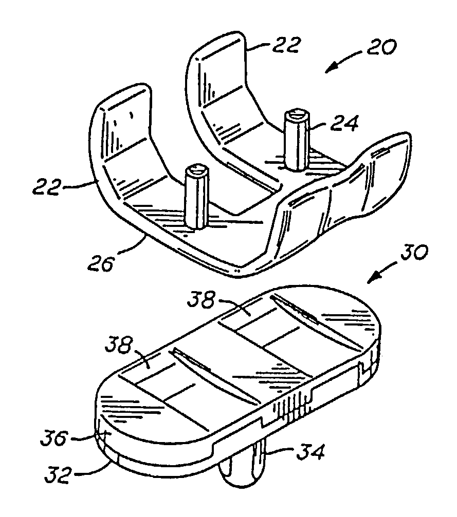
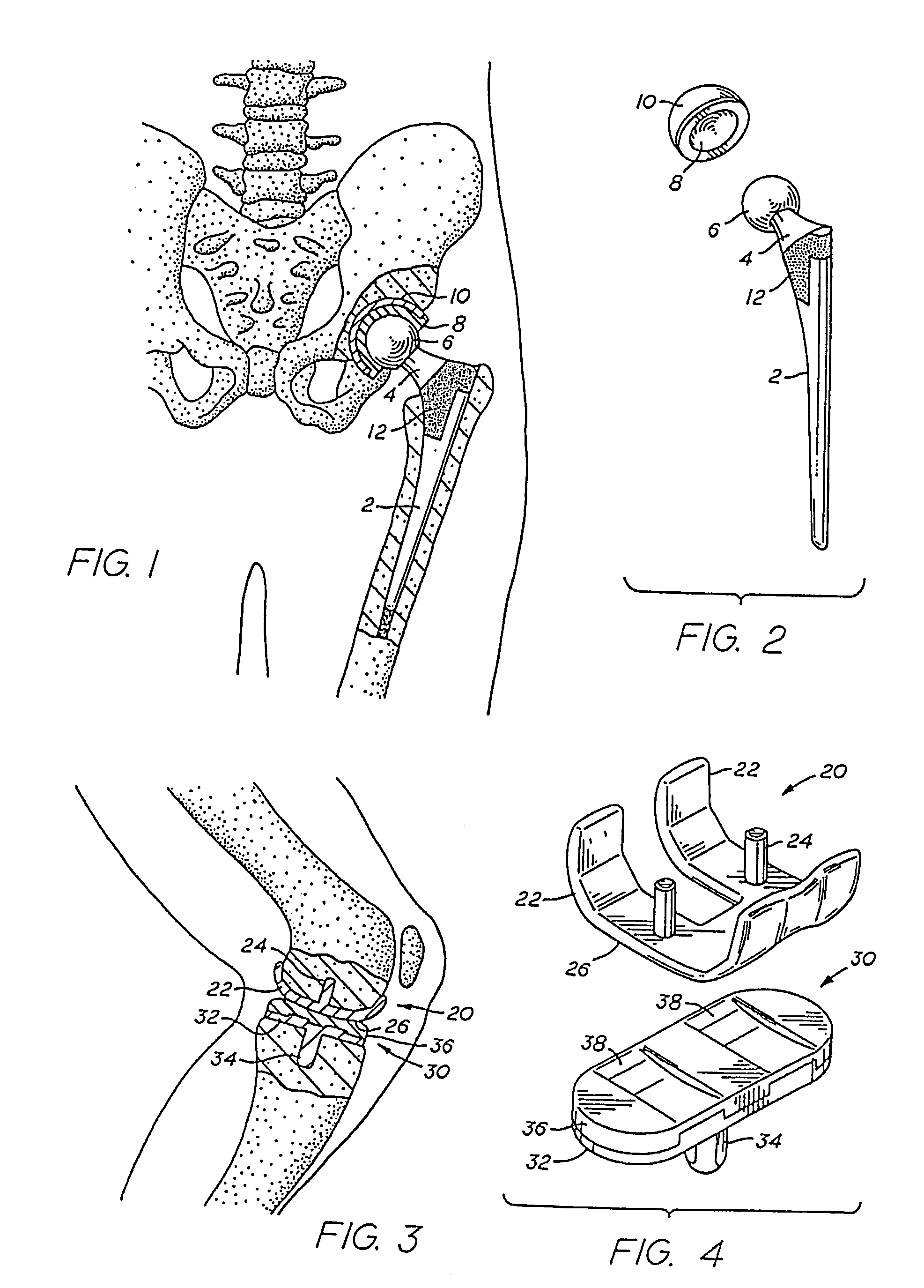
[0038]One aspect of the present invention is to provide a method for forming an oxide coating of uniform thickness on zirconium or a zirconium alloy, the zirconium or zirconium alloy each having a single phase crystalline structure and uniform composition and an altered surface roughness. Another aspect of the present invention is to provide a low friction, wear resistant oxide coating of uniform thickness on prosthesis surfaces, such as articulating surfaces and irregular surface structures adapted to accommodate tissue ingrowth on a portion of the prosthesis body.

[0039]The subject method of forming an oxide coating of uniform thickness by inducing an altered surface roughness on zirconium or a zirconium alloy, each having a single phase crystalline structure and uniform composition, prior to oxidizing the zirconium or zirconium alloy is applicable to various prosthetic parts and devices. These prosthetic parts and devices include, but are not limited to, cardiovascular implants in...


PUM

PropertyMeasurementUnit
thicknessaaaaaaaaaa
thicknessaaaaaaaaaa
thickaaaaaaaaaa

Abstract

A coating of blue-black or black oxidized zirconium of uniform and controlled thickness on a zirconium or zirconium alloy material is accomplished through the use of a single phase crystalline material substrate having an altered surface roughness. An oxidized zirconium coating of uniform and controlled thickness is especially useful on orthopedic implants of zirconium or zirconium-based alloys to provide low friction, highly wear resistant surfaces on artificial joints, such as, but not limited to, hip joints, knee joints, shoulders, elbows, and spinal implants. The uniformly thick oxidized zirconium surface of controlled depth on prostheses provide a barrier against implant corrosion caused by ionization of the metal prostheses. The invention is also useful in non-articulating implant devices such as bone plates, bone screws, etc.

Description

[0001]This application claims priority to, and is a divisional application of, U.S. application Ser. No. 09 / 909,612 filed Jul. 20, 2001, now U.S. Pat. No. 6,585,772 which is a continuation-in-part of U.S. application Ser. No. 09 / 381,217, filed Nov. 24, 1999, now U.S. Pat. No. 6,447,550, issued Sep. 10, 2002, which is a United States National Stage of International Application No. PCT / US98 / 06059, filed Mar. 27, 1998, and claims priority to U.S. Provisional Application Ser. No. 60 / 042,364, filed Mar. 27, 1997, (which are hereby incorporated by reference for all purposes).BACKGROUND OF THE INVENTION[0002]This invention relates to metallic implants with load bearing surfaces coated with a thin, dense, low friction, highly wear-resistant, uniformly thick coating of oxidized zirconium.[0003]The invention also relates to uniformly thick oxidized zirconium coatings on the non-load bearing surfaces of an orthopedic implant where the oxidized zirconium provides a barrier between the metallic ...

Claims


Application Information

Patent Timeline
Patent Type & Authority Patents(United States)
IPC IPC(8): A61F2/38A61F2/00A61F2/28A61L27/00A61F2/30A61F2/32A61F2/34A61F2/36A61F2/40A61F2/42A61F2/44A61L27/04A61L27/30C23C8/02C23C8/10C23C8/12
CPCC23C8/10A61L27/047A61L27/306C23C8/02A61F2/30767A61F2/2803A61F2/3094A61F2/32A61F2/34A61F2/36A61F2/3662A61F2/367A61F2/38A61F2/3859A61F2/389A61F2/40A61F2/4241A61F2/44A61F2002/30322A61F2002/30332A61F2002/30838A61F2002/30878A61F2002/30892A61F2002/30909A61F2002/3611A61F2002/3625A61F2002/365A61F2220/0033A61F2250/0026A61F2310/00089A61F2310/00634
Inventor HUNTER, GORDONASGIAN, CATHERINE M.HINES, GARY L.
Owner SMITH & NEPHEW INC
Why Eureka
Try Eureka