

Induction-heated reactors for gas phase catalyzed reactions
a gas phase catalytic reaction and induction heating technology, which is applied in the direction of electric/magnetic/electromagnetic heating, gas-gas reaction process, physical/chemical process catalyst, etc., can solve the problems of insufficient surface area, inefficient heating of too low frequency, and insufficient induction heating of gas-permeable metallic structures in the prior ar
- Summary
- Abstract
- Description
- Claims
- Application Information
AI Technical Summary
Benefits of technology
Problems solved by technology
Method used
Image

Examples
example 1
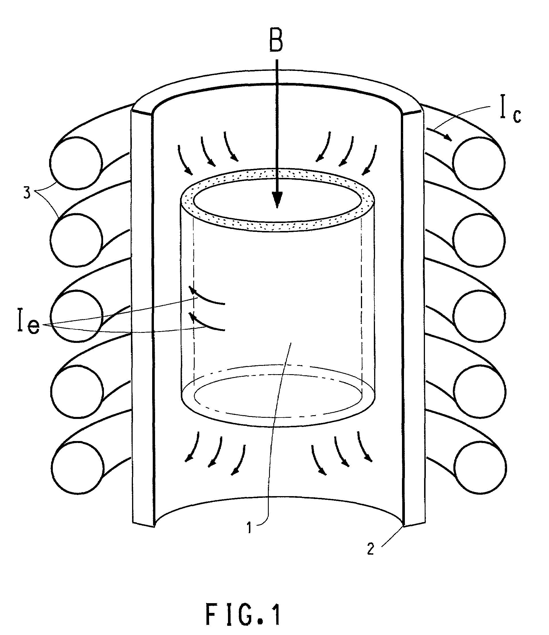
[0044]This Example demonstrates that the catalyst / susceptor of the present invention can be heated uniformly and with high efficiency by induction heating at low induction frequency. In a manner similar to that of FIG. 2, a cylindrical catalyst / susceptor was constructed by wrapping a strip of platinum alloy gauze thirty-six (36) times around a quartz tube. The platinum alloy comprised 90% platinum and 10% rhodium. The gauze was of an 80 mesh weave and a width of 40.6 cm (16 inches), and had a wire size of 0.076 mm (0.003 inch). The bulk resistivity of platinum gauze was measured to be 85×10−6 ohm-cm. Therefore the maximum induction heating efficiency can be obtained at the frequency of 425 Hz, which is among the lowest frequencies used in induction heating industry. The quartz tube had an outer diameter of 30.5 cm (12″). The resulting catalyst / susceptor had an inner radius of 15.24 cm and a thickness of about 0.6 cm. The catalyst / susceptor structure was placed in a water-cooled indu...
examples 2 – 8
EXAMPLES 2–8
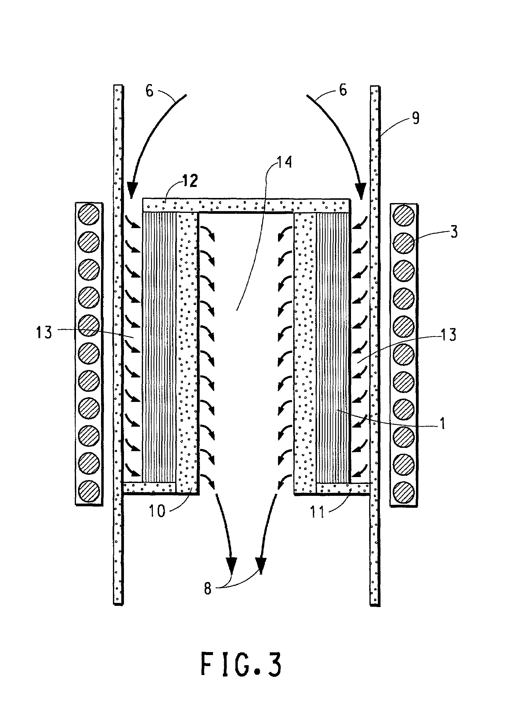
[0045]HCN was prepared by reacting a slight molar excess of ammonia with methane in an inductively heated continuous radial flow fixed bed reactor system as illustrated in FIG. 3. The catalyst / susceptor used in this experiment was a single cylinder of 90 / 10 Pt / Rh wire of diameter 0.003 inch, 80 mesh gauze. The cylinder measured 1.25 inches outside diameter and 1.5 inches high. The cylinder was constructed by wrapping 23 layers of the Pt / Rh gauze around a 1 inch diameter perforated quartz tube (gas-permeable tube 10 of FIG. 3) made up of about forty percent (40%) openings. The total wrapped thickness of the catalyst / susceptor was about 0.12–0.13 inches. The single cylinder of catalyst / susceptor was mounted as a concentric cylinder inside the larger induction coil cylinder. Reactants were fed to the catalyst / susceptor in a radial direction with product gases exiting through the center of the perforated quartz tube. Temperature was controlled by monitoring a single bulk exi...
examples 9 – 16
EXAMPLES 9–16
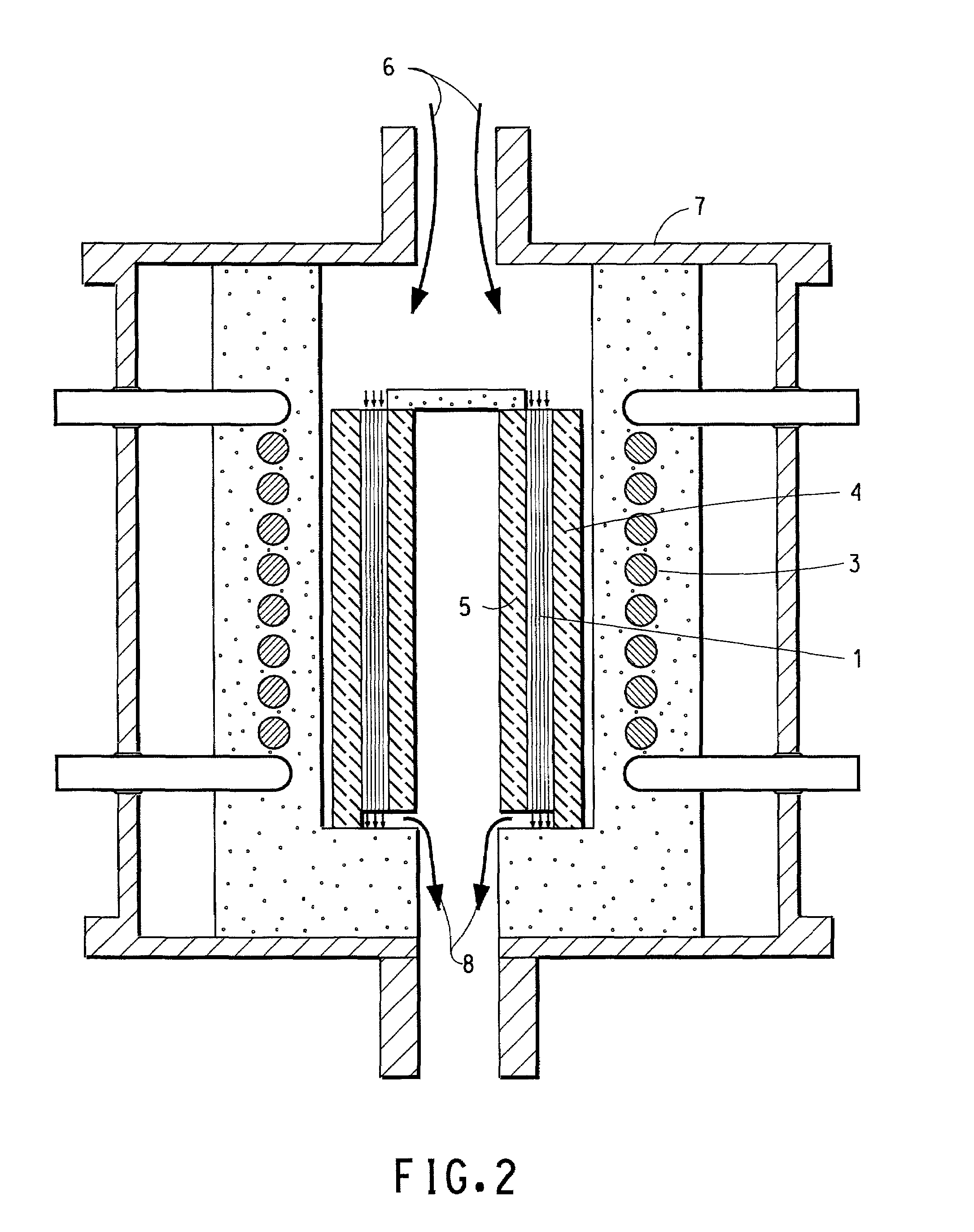
[0047]Examples 9–16 illustrate performance of an axial flow arrangement through the single catalyst / susceptor cylinder. HCN was prepared by reacting a slight molar excess of ammonia with methane in an inductively heated continuous flow fixed bed reactor system illustrated in FIG. 2. The catalyst / susceptor used in this experiment was a single cylinder of 90 / 10 Pt / Rh gauze which measured 0.75 inch OD×0.50 inch ID×1.50 inches high. The catalyst / susceptor was constructed by wrapping 23 layers of Pt / Rh gauze around a 1.3 cm (0.50 inch) diameter solid quartz tube. The cylindrical catalyst / susceptor, having a cross sectional area of 0.245 in2, was then inserted inside a 0.75 inch ID quartz reactor tube, forming a snug fit. The reactor tube was then placed inside a slightly larger induction coil cylinder. Reactants were fed to the catalyst in an axial direction with product gases exiting through the annulus formed between the two concentric quartz tubes. Temperature was control...
PUM
| Property | Measurement | Unit |
|---|---|---|
| frequencies | aaaaa | aaaaa |
| operating temperature | aaaaa | aaaaa |
| frequencies | aaaaa | aaaaa |
Abstract
Description
Claims
Application Information