Hot solids gasifier with CO2 removal and hydrogen production

a gasifier and hot solids technology, applied in the direction of hydrogen/synthetic gas production, gas modification by gas mixing, hydrogen/synthetic gas production, etc., can solve the problems of large capital equipment requirements, insufficient reductions, and insufficient reductions to achieve atmospheric cosub>2 /sub>stabilization

Active Publication Date: 2006-08-01
AIR PROD & CHEM INC +1
View PDF1 Cites 72 Cited by
  • Summary
  • Abstract
  • Description
  • Claims
  • Application Information

AI Technical Summary

Benefits of technology

[0013]The calciner may include a calciner vessel having the CaCO3 inlet and CaO outlet and a combustor in fluid communication with the calciner vessel, the combustor having an air inlet and a CaS inlet. Air and CaS combusted in the combustor produces hot sorbent particles which are discharged to the calciner vessel, the heat content of the sorbent particles calcining the CaCO3 to produce CaO and CO2. A settling chamber is disposed intermediate the combustor and the calciner vessel such that hot sorbent particles entrained in flue gas discharged from the combustor enter the settling chamber, where hot heavy sorbent particles fall out the flue gas and enter the calciner. The flue gas and entrained light sorbent particles are discharged to a first separator, where the fine sorbent particles are separated from the flue gas. The CaO and the CO2 produced by calcining the CaCO3 are discharged from the calciner vessel to a second separator. CO2 produced by calcining the CaCO3 is also discharged through a bypass line. A bypass valve controls the CO2 flow distribution between the separator and the bypass line, thereby limiting the exit velocity of the CO2 to the separator to prevent entrainment of heavy sorbent particles in the exiting CO2. The second separator discharges the CaO to the shift reactor.
[0015]It is also an object of the invention to provide a gasifier which captures carbon dioxide, generated during production a medium Btu syngas, more efficiently than conventional methods.

Problems solved by technology

Although substantial reductions in emissions of CO2 could be achieved by increase in efficiency of energy conversion and utilization, such reductions may not be sufficient to achieve atmospheric CO2 stabilization.
A substantial energy penalty is incurred using this process due to the large power requirements of producing pure oxygen.
Unfortunately, substantial capital equipment is required.

Method used


Image

  • Hot solids gasifier with CO2 removal and hydrogen production
  • Hot solids gasifier with CO2 removal and hydrogen production
  • Hot solids gasifier with CO2 removal and hydrogen production

Examples


first embodiment

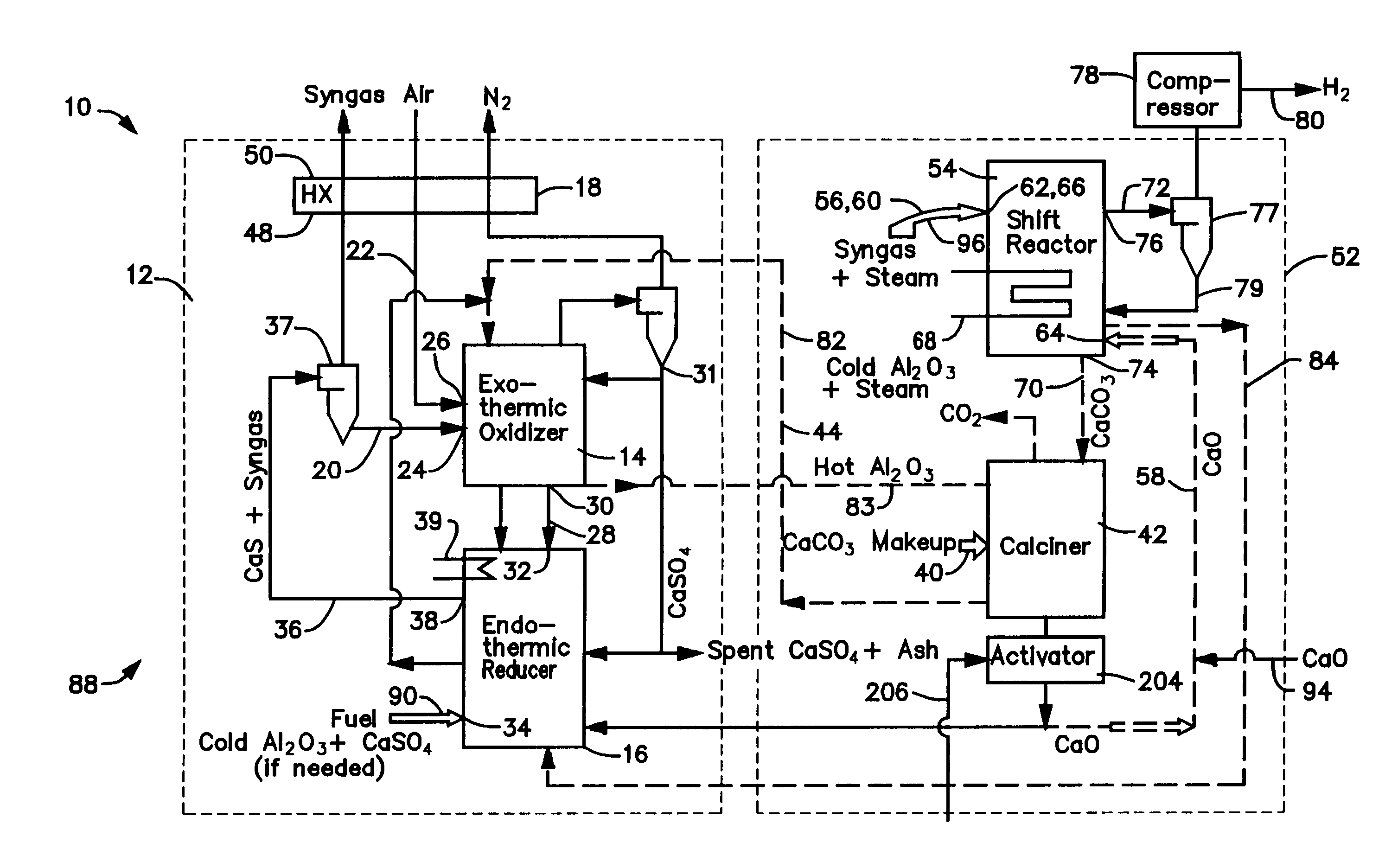
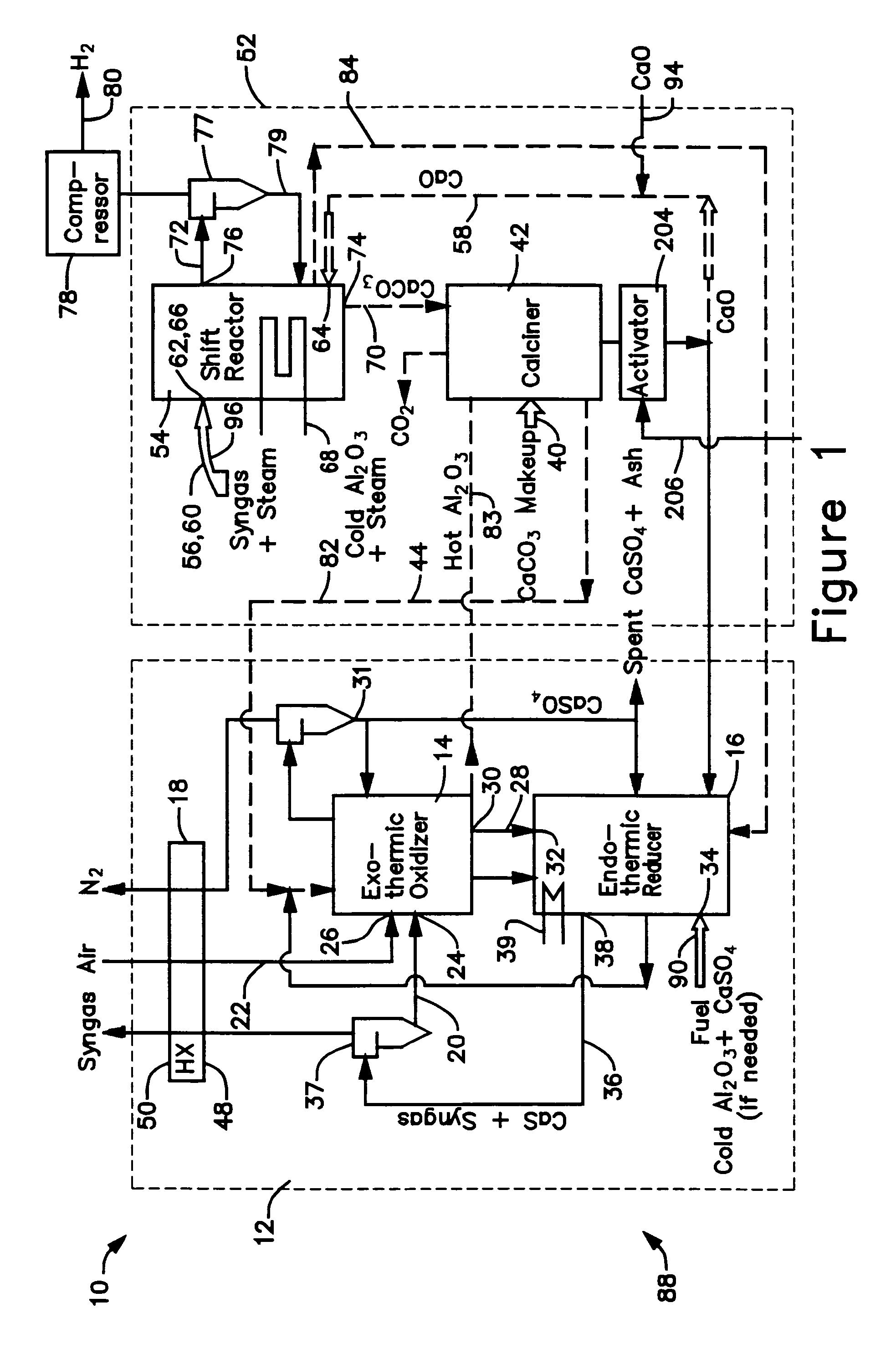
[0030]The calciner 42 in the CaO / CaCO3 loop 52 is a high temperature endothermic reactor that receives its heat from the oxidizer reactor 14 in the CaS / CaSO4 loop 12. In a thermal process loop 82, 83 transferring heat from the oxidizer reactor 14 to the calciner 42 (FIG. 1), a heat exchange mass in the form of inert particles, such as bauxite (Al2O3) particles or sorbent (CaO, CaCO3, CaS, CaSO4) particles is circulated 82, 83 between the oxidizer reactor 14 and the calciner 42 via interconnecting piping. The bauxite, CaO, CaS, and CaSO4 is chemically inert in the calciner and can be separated from the reactants of either chemical process loop 12, 52 allowing the heat to be balanced independent of the mass balance of the chemically active material. Any bauxite which is lost during the operating cycle of the gasifier 10 may be made-up by adding, along the path 90, new bauxite particles through an inlet 34 to the reducer reactor 16.

second embodiment

[0031]With reference to FIGS. 3 and 4, sorbent (CaO, CaCO3, CaS, CaSO4) particles and coal (carbon) particles are the primary heat transfer mass in the gasifier 10′. Bauxite particles may be utilized to provide for any heat transfer mass that is required for operation but which is not provided by the sorbent and coal particles. The raw coal utilized by the gasifier 10′ is fed along a path 92 into the shift reactor 54 through an inlet (along with the lime and steam 94, 96). The high temperature generated by the exothermic reaction producing the CaCO3 devolatize and partially decarbonate the coal, with the resulting char, in the form of “heavies” and “lights”, being discharged along paths 98, 100 from the shift reactor 54 through a pair of outlets 102, 104 which are connected to a pair of inlets 106, 108 on the reducer reactor 16. CaCO3 particles, in the form of lights, are also discharged 100 from the shift reactor 54. The flow of lights is received in a separator 110, where the smal...

embodiment 10

[0032]In the thermal process loop 84, 85 of this embodiment 10′, the reducer reactor 16 comprises three sections, a char gasifier 116, a char combustor 118 and a carbon burn-out cell 120. As shown in FIG. 4, the char gasifier heavies and lights inlets 106, 108 are connected to the shift reactor heavies outlet 102 and the separator lights outlet 122 as described above. In addition, a gas outlet 124 of the char gasifier 116 is connected to a gas inlet 126 of the shift reactor 54 and a gas inlet 128 and a char outlet 130 of the char gasifier 116 are connected to a gas outlet 132 and a char inlet 134 of the char combustor 118. The char combustor 118 also has a char outlet 136 connected to a char inlet 138 of the carbon bum-out cell 120, a gas inlet 139 connected to a gas outlet 141 of the carbon burn-out cell 120, and a CaSO4 inlet 140 connected to an outlet of the oxidizer reactor 14. The carbon bum-out cell 120 also has a GaS / fuel outlet 142 connected to an inlet of the oxidizer react...


PUM

PropertyMeasurementUnit
temperatureaaaaaaaaaa

Abstract

A gasifier 10 includes a first chemical process loop 12 having an exothermic oxidizer reactor 14 and an endothermic reducer reactor 16. CaS is oxidized in air in the oxidizer reactor 14 to form hot CaSO4 which is discharged to the reducer reactor 16. Hot CaSO4 and carbonaceous fuel received in the reducer reactor 16 undergo an endothermic reaction utilizing the heat content of the CaSO4, the carbonaceous fuel stripping the oxygen from the CaSO4 to form CaS and a CO rich syngas. The CaS is discharged to the oxidizer reactor 14 and the syngas is discharged to a second chemical process loop 52. The second chemical process loop 52 has a water-gas shift reactor 54 and a calciner 42. The CO of the syngas reacts with gaseous H2O in the shift reactor 54 to produce H2 and CO2. The CO2 is captured by CaO to form hot CaCO3 in an exothermic reaction. The hot CaCO3 is discharged to the calciner 42, the heat content of the CaCO3 being used to strip the CO2 from the CaO in an endothermic reaction in the calciner, with the CaO being discharged from the calciner 42 to the shift reactor 54.

Description

BACKGROUND OF THE INVENTION[0001]This invention relates generally to apparatus for producing hydrogen. More particularly, the present invention relates to apparatus utilizing fossil fuels, biomass, petroleum coke, or any other carbon bearing fuel to produce hydrogen for power generation which minimizes or eliminates the release of carbon dioxide (CO2).[0002]Fossil fuel power stations conventionally use steam turbines to convert heat into electricity. Conversion efficiencies of new steam power stations can exceed 40% on a lower heating value basis (LHV). New supercritical steam boiler designs, relying on new materials, allow higher steam temperatures and pressures, providing efficiencies of close to 50% LHV and further improvements might be expected. Significant advancements have also been made in combined cycle gas turbines (CCFTs). A gas turbine can withstand much higher inlet temperatures than a steam turbine. This factor produces considerable increases in overall efficiency. The ...

Claims


Application Information

Patent Timeline
Patent Type & Authority Patents(United States)
IPC IPC(8): C10B1/00B01J10/00B01J8/00C10J3/00F27B5/00C01B3/10C01B3/56C10J3/54C10J3/56
CPCC01B3/105C01B3/56C10J3/54C10J3/56F23J15/04B01D53/96Y02E20/18C01B2203/0283C01B2203/042C01B2203/0475C01B2203/86C10J2300/093C10J2300/0956C10J2300/0973C10J2300/0983C10J2300/1618C10J2300/1637C10J2300/1861C10J2300/1869C10J2300/1884F23J2215/50F23J2219/60Y02E60/36Y02E20/185Y02E20/16B01D2258/0283Y02P20/151Y02P30/00
Inventor ANDRUS JR., HERBERT E.MCCARTNEY, MICHAEL S.
Owner AIR PROD & CHEM INC
Why Eureka
Try Eureka