Nuclear magnetic resonance apparatus probe

a nuclear magnetic resonance and apparatus technology, applied in the field of nuclear magnetic resonance apparatus probes, can solve the problems of multiple resonance, resonating frequency, and difficulty in installing a plurality of coils to permit simultaneous measurement of different nuclides, and achieve the effects of increasing q-value, high sensitivity, and small resistance of the probe coil

Inactive Publication Date: 2006-08-01
HITACHI LTD
View PDF30 Cites 10 Cited by
  • Summary
  • Abstract
  • Description
  • Claims
  • Application Information

AI Technical Summary

Benefits of technology

[0015]In an embodiment, there is preferably provided a nuclear magnetic resonance apparatus probe, wherein resonance frequencies of the saddle type coils and the solenoid coil can be adjusted by a capacitor, a coil, and a resistor that are electrically connected to each other, or a combination thereof, and it is possible to adjust so that the resonance frequency of the saddle type coils coincides with that of the solenoid coil. According to the arrangement, it is possible through adjustments to bring the resonance frequency of the saddle type coils into coincidence with the resonance frequency of the solenoid coil and use the saddle type coils offering a poor sensitivity for an exclusive use for irradiation of an RF pulse magnetic field and the solenoid coil offering a good sensitivity for an exclusive use for reception of the FID signal. This makes it possible, in the solenoid coil, to expedite decay in an induced current caused by an application of the RF pulse magnetic field, thus allowing the FID signal to be received immediately after the RF pulse magnetic field has been applied.
[0022]Preferably the saddle type coil irradiates the RF pulse magnetic field and the solenoid coil receives the FID signal. This makes it possible to receive the FID signal immediately after the RF pulse magnetic field has been applied.

Problems solved by technology

Since it is necessary, with the superconducting magnet that produces the magnetic field in the perpendicular direction, to irradiate the sample with the RF pulse magnetic field in the horizontal direction, however, it is impracticable to wind the solenoid coil around a sample tube in the perpendicular direction containing therein an aqueous solution of protein, and thus it is not commonly used.
In order to employ a solenoid coil as the probe coil, there is a problem that it is difficult to install a plurality of coils to permit simultaneous measurement of different nuclides, or what is called multiple resonance.
As is known from equation 1 and equation 2, it is possible to define the resonance frequency fo and the Q-value by the combination of inductance L and capacitance L; however, a different nuclide results in a different resonating frequency and it is difficult to implement multiple resonance using a simple circuit.
According to the first method, the low Q-value results in a radiation loss of the RF pulse and, in addition, the FID signal is small, which makes it difficult to improve the S / N ratio.
In the second method, it is difficult to implement quick switching.
In the third method, interference caused by electromagnetic induction among different coils presents a problem.
In a nuclear magnetic resonance apparatus having a static magnetic field in a horizontal direction and employing a solenoid coil as the probe coil, however, it is geometrically impossible to dispose a plurality of solenoid coils so as to be orthogonal to each other around the sample tube, thus being unable to realize multiple resonance.

Method used


Image

  • Nuclear magnetic resonance apparatus probe
  • Nuclear magnetic resonance apparatus probe
  • Nuclear magnetic resonance apparatus probe

Examples


embodiment 1

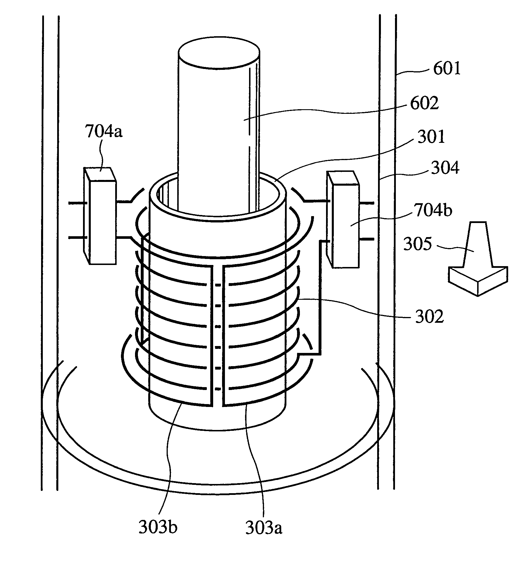
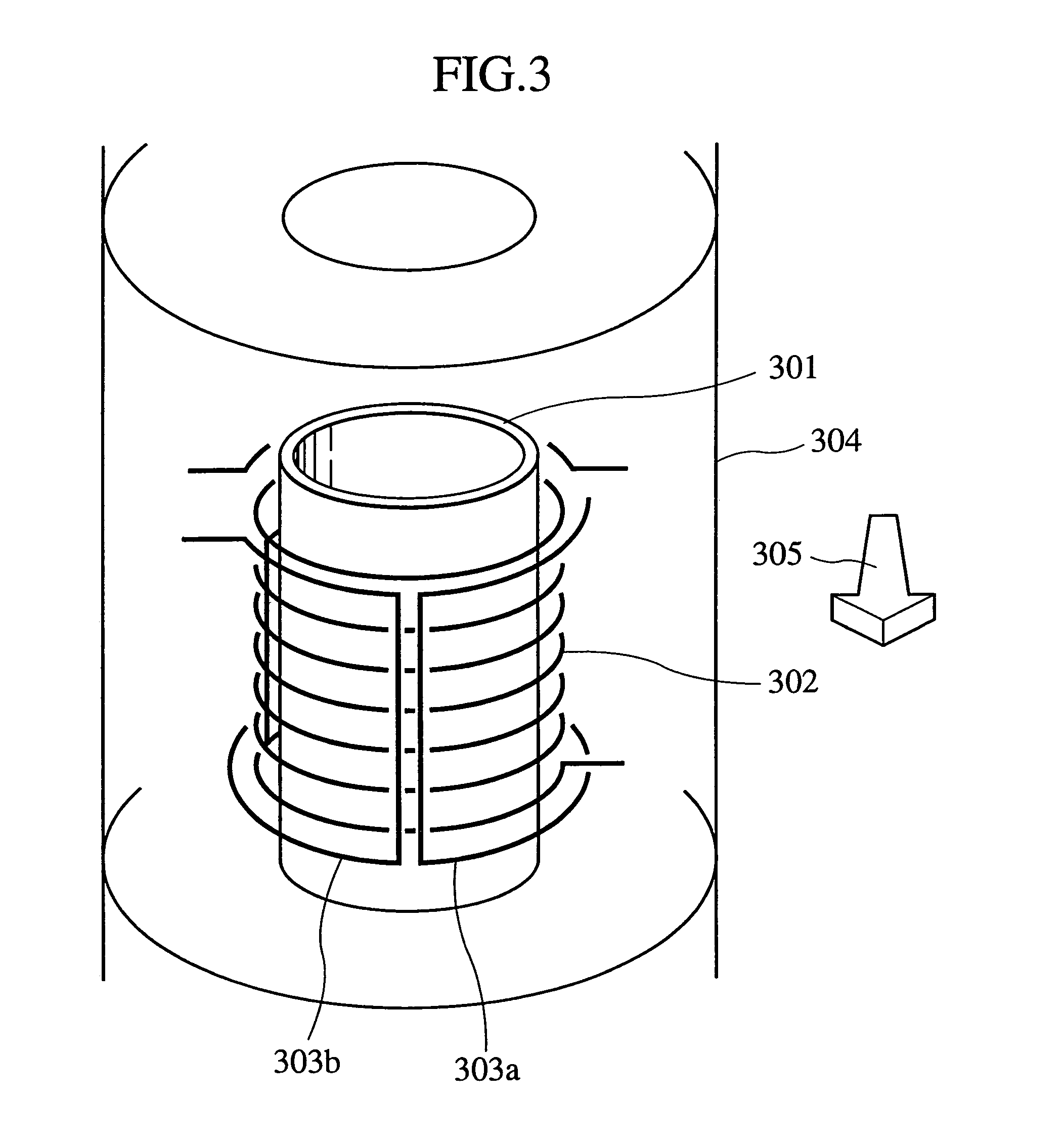
[0032]FIG. 3 shows a first embodiment according to the present invention. FIG. 3 is a structural view showing an area near a probe coil of a nuclear magnetic resonance apparatus probe according to the present invention. It shows a principal point of the present invention.

[0033]A bobbin 301 is of a cylindrical shape, for which special glass having a relative permeability of a value close to 1 is used as a material thereof. The bobbin 301 has a structure that allows a sample tube containing therein a sample to be inserted therein. It is important that the bobbin 301 be made of a material that does not emit a nuclear magnetic resonance signal, since it is disposed inside a solenoid coil 302. Although no specific material is named as long as the material does not emit the nuclear magnetic resonance signal, it is desirable that glass or the like be used for reasons of ease of manufacture. In addition, since it is necessary to ensure that a homogeneous static magnetic field generated by a...

embodiment 2

[0036]FIG. 8 shows a second embodiment according to the present invention. FIG. 8 is a structural view showing an area near a probe coil of a nuclear magnetic resonance apparatus probe according to the present invention. It shows a principal point of the present invention.

[0037]Embodiment 2 has substantially the same construction as that of embodiment 1, except that, since capacitance-variable capacitors 801a, 801b are built into the solenoid coil 302 and the saddle type coils 303a, 303b of the probe, the resonance frequency can be adjusted by adjusting these capacitors. It is possible to vary the resonance frequency by not only adjusting the capacitance component, but also adjusting an inductance component. Moreover, it is possible to vary the Q-value by adjusting a resistance component. The resonance frequency can therefore be varied by inserting element parts having the capacitance component, inductance component, and resistance component, respectively, in any desired circuit poi...

embodiment 3

[0038]A third embodiment according to the present invention will be explained in the following. The construction of an area near a probe coil of a nuclear magnetic resonance probe according to embodiment 3 is exactly the same as that of embodiment 1 shown in FIG. 3. A block diagram showing the probe built into a nuclear magnetic resonance apparatus is shown in a block diagram (FIG. 4) for embodiment 1. It goes without saying that a block diagram (FIG. 5) for embodiment 2 may still be perfectly all right for serving the purpose. Embodiment 3 is characterized in that a superconductor is used in part or all of the solenoid coil 302 and the saddle type coils 303a, 303b.

[0039]There are two specific benefits involved in using a superconductor for a coil conductor. First, it improves the Q-value. As shown in equation 2 noted earlier, the Q-value is inversely proportional to an electrical resistance R in a circuit. The Q-value can therefore be improved by using a superconductor having zero...


PUM

PropertyMeasurementUnit
inductanceaaaaaaaaaa
axial lengthaaaaaaaaaa
diameteraaaaaaaaaa

Abstract

A nuclear magnetic resonance apparatus comprises a superconducting magnet that produces a static magnetic field, a probe having a probe coil that irradiates an RF pulse magnetic field and receives a free induction decay signal (FID signal) emitted therefrom, an RF power source that supplies the probe with an RF current, an amplifier that amplifies the FID signal, a detector that detects a signal, and an analyzer that analyzes the signal detected by the detector, wherein the probe coil includes a solenoid coil and a saddle type coil.

Description

CROSS-REFERENCE TO RELATED APPLICATION[0001]This application is a continuation of U.S. patent application Ser. No.: 10 / 291,690, filed on Nov. 12, 2002 now U.S. Pat. No. 6,828,791, the subject matter of which is incorporated in its entirety by reference herein.BACKGROUND OF THE INVENTION[0002]The present invention relates to a nuclear magnetic resonance apparatus probe and a nuclear magnetic resonance apparatus using the same.[0003]Analysis methods for organic substances employing nuclear magnetic resonance have been making a rapid progress these days. In particular, when the methods are combined with a powerful superconducting magnet technology, it has become possible to make an efficient structural analysis on an atomic level of organic compounds, such as protein having a complicated molecular structure. The present invention is concerned with a nuclear magnetic resonance apparatus used for analyzing the structure and interaction on an atomic level of protein molecules in an aqueou...

Claims


Application Information

Patent Timeline
Patent Type & Authority Patents(United States)
IPC IPC(8): G01V3/00G01R33/34G01R33/36H01F5/00
CPCG01R33/30G01R33/34061G01R33/34069G01R33/34053G01R33/34023G01R33/34092
Inventor MORITA, HIROSHIOKADA, MICHIYAKAKUGAWA, SHIGERUAIHARA, KATSUZOU
Owner HITACHI LTD
Why Eureka
Try Eureka