Focused particle beam systems and methods using a tilt column

a technology of focused particle beams and beam systems, applied in the direction of mass spectrometers, nuclear engineering, stability-of-path spectrometers, etc., can solve the problems of large system weight, high cost of cleanroom fabrication space, and inability to meet the requirements of the work stage, so as to improve the stability of the work stage assembly

Inactive Publication Date: 2006-08-22
FSI CORP
View PDF21 Cites 18 Cited by
  • Summary
  • Abstract
  • Description
  • Claims
  • Application Information

AI Technical Summary

Benefits of technology

[0010]It is another object of the invention to improve the stabil

Problems solved by technology

Existing FIB systems which incorporate a tilting stage experience several problems.
A tilting work stage, which is large relative to many of the other components of a FIB system, causes the system to be relatively bulky.
Such a large bulk is disadvantageous because cleanroom fabrication space is expensive.
A tilting work stage also causes an FIB system to be unstable because a tilting work stage can make an FIB system susceptible to low frequency vibration and gravity sag, as discussed further below.
Disadvantageously, the vibration of and the changing configuration of a tilting work stage can interfere with the performance of a system component, such as a laser interferometer.
Low frequency vibration reduces resolution of a focused particle beam system by adding uncertainty in the determination of the location of the target point, i.e. where the ion beam interacts with the

Method used


Image

  • Focused particle beam systems and methods using a tilt column
  • Focused particle beam systems and methods using a tilt column
  • Focused particle beam systems and methods using a tilt column

Examples


Embodiment Construction

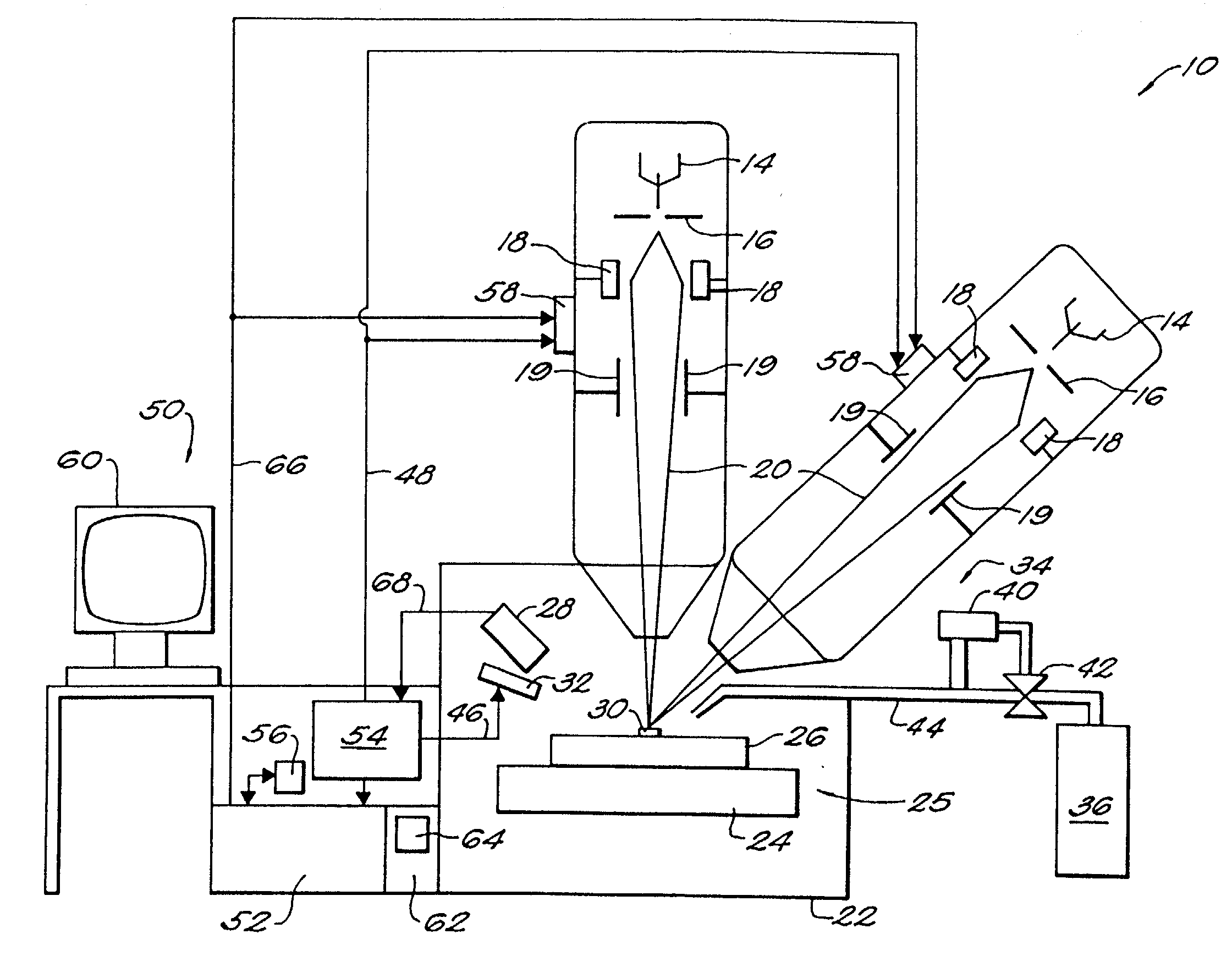
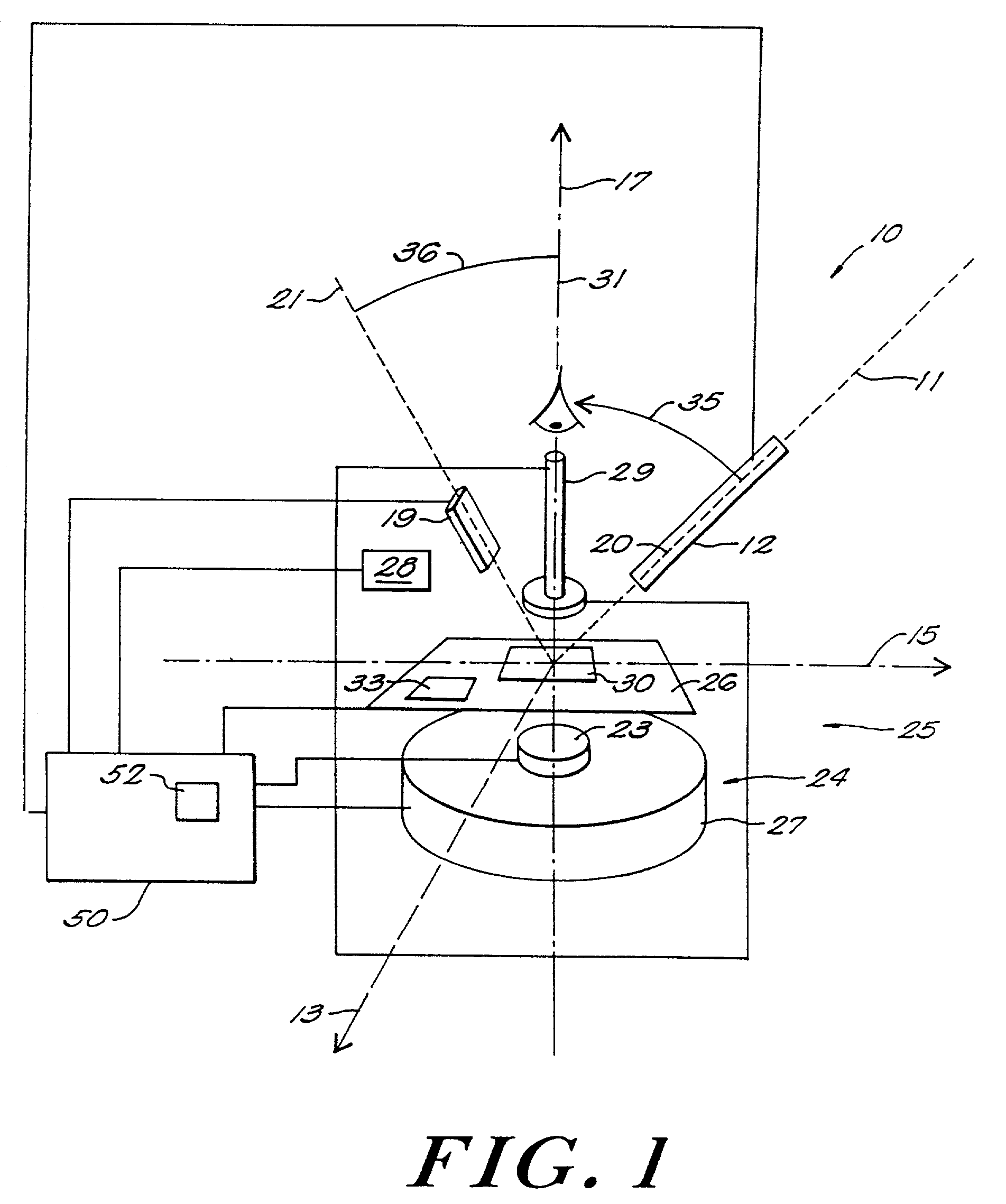
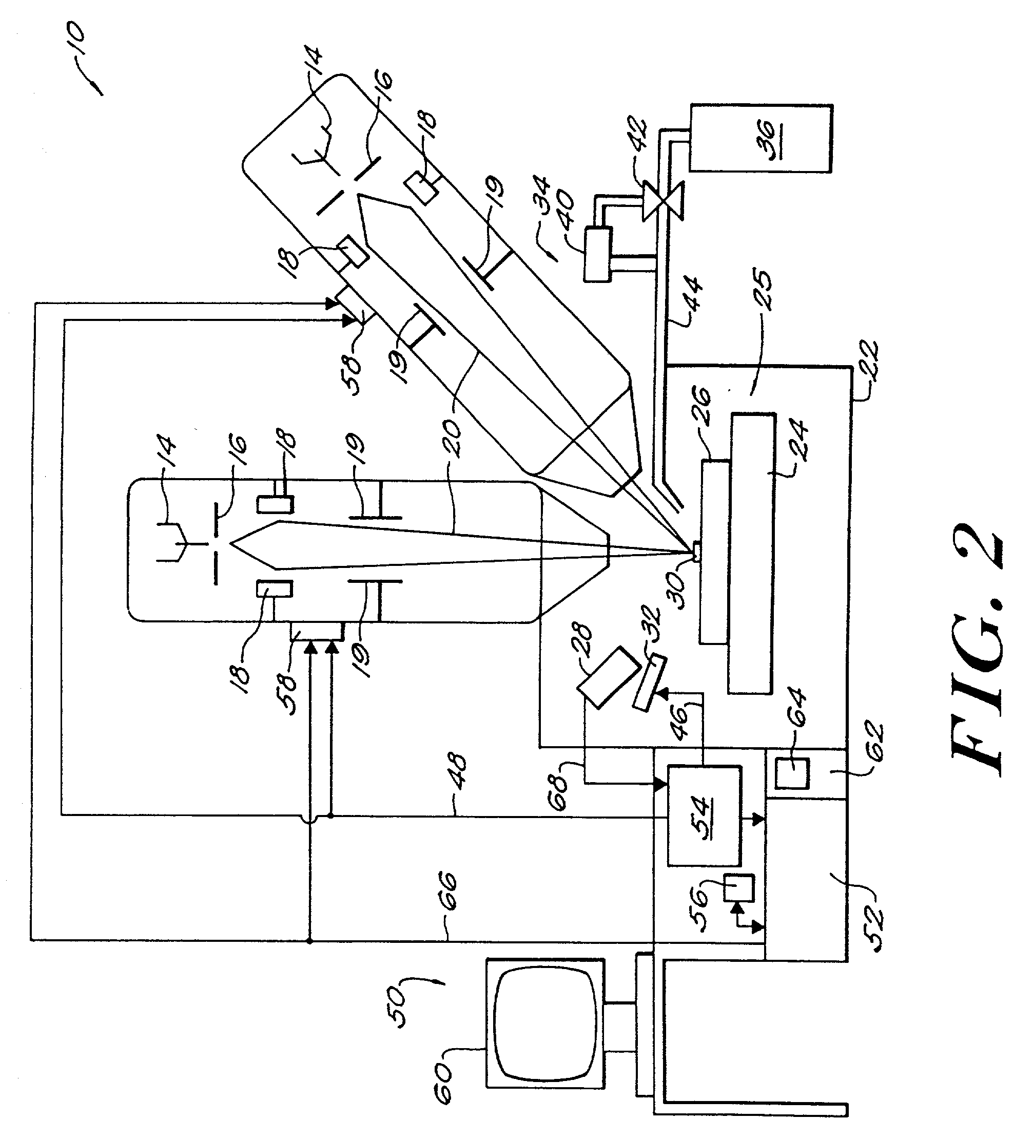
[0051]The system 10 illustrated in FIG. 1 with a tilted ion beam column 12 can etch a cavity in a sample to create a vertical cross-section and then image the vertical cross-section without tilting the work stage assembly 25. FIG. 1 depicts one embodiment of a focused particle beam system 10 according to the invention for interacting with a workpiece 30. The system 10 of FIG. 1 includes a tilted ion column 12, a vacuum chamber 22, and a work stage assembly 25. The system 10 provides a focused particle beam system that can precisely etch and image a cross-section of a sample or workpiece 30, e.g., a wafer containing semiconductor devices. The sample is seated within the vacuum chamber 22 and operated on by a particle beam generated by the tilted column 12 to create cross-sectional images. The images are used to analyze material defects found in the wafer, and can provide process engineers with timely data without removing the wafer from the production line.

[0052]Part of the ion colum...


PUM

PropertyMeasurementUnit
Angleaaaaaaaaaa
Angleaaaaaaaaaa
Angleaaaaaaaaaa

Abstract

Particle beam systems and methods for interacting with a workpiece according to this invention include a work stage assembly and a first particle beam source. The work stage assembly is adapted a) for supporting a workpiece, b) for translating along a first axis, c) for translating along a second axis perpendicular to the first axis, and d) for rotating about a third axis perpendicular to both the first axis and the second axis. The work stage assembly has a work stage axis substantially parallel to the third axis. The first particle beam source for interacting with the workpiece is supported by the work stage assembly. The first particle beam source has a first particle beam axis. In one embodiment, the first particle beam source is oriented so that the first particle beam axis forms an angle with the third axis. In another embodiment, the first particle beam source is tiltable from a first position, with the first particle beam axis substantially parallel to the third axis, to a second position, with the first particle beam axis forming an angle with the third axis. Thus, the particle beam system can etch and image a vertical cross-section of the workpiece without offsetting the work stage axis from the third axis.

Description

[0001]This application claims priority from pending U.S. patent application No. 09 / 359,534, filed Jul. 22, 1999, which claims priority from U.S. patent application No. 09 / 022,065 field Feb. 11, 1998 and issued Mar. 21, 2000 as U.S. Pat. No. 6,039,000.BACKGROUND OF THE INVENTION[0002]The present invention relates to focused particle beam systems and methods for processing a workpiece, e.g., etching and imaging a cross-section of a workpiece.[0003]Present focused ion beam (FIB) systems typically include an ion beam column oriented normal to the workpiece and a tilting work stage. Such systems can include an electron column offset from the normal to the workpiece. To image a cross-section of a workpiece using an ion column, existing systems etch a cavity in the workpiece and tilt the stage so that the ion beam can impinge on a side wall of the cavity.[0004]Existing FIB systems which incorporate a tilting stage experience several problems. A tilting work stage, which is large relative t...

Claims


Application Information

Patent Timeline
IPC IPC(8): C23F1/12C23C16/48H01J37/08H01L21/306H01J37/305H01L21/263
CPCH01J37/3056H01L21/2633H01J2237/31745H01J2237/31744
Inventor LIBBY, CHARLES J.WARD, BILLY W.
Owner FSI CORP
Why Eureka
Try Eureka