Implementation of microfluidic components, including molecular fractionation devices, in a microfluidic system

a microfluidic system and microfluidic components technology, applied in the field of microfluidic systems, can solve the problems of complex sample handling requirements, large sample preparation requirements, and limited current technology in the ability to recognize alterations in functional and structural properties of proteins, and no little or no functional information is revealed

Inactive Publication Date: 2006-08-22
CYTONOMEST
View PDF37 Cites 48 Cited by
  • Summary
  • Abstract
  • Description
  • Claims
  • Application Information

AI Technical Summary

Benefits of technology

[0024]A plurality of molecular fractionation device may be implemented in a multidimensional programmable affinity fractionation system for protein identification, extraction, elution and dispensing. Such a system incorporates a set of technologies that can separate proteins using biochemical molecular criteria in addition to physical properties such as molecular weight and isoelectric focusing. Affinity fractionation provides an additional dimension that provides the ability to distinguish between molecules whose amino acid sequences are identical but which differ in expression levels and post-translational modifications and hence functionality.

Problems solved by technology

Available state-of-the-art analytical methodologies for protein expression profiling require extensive sample preparation and have complex sample handling requirements.
Current technologies are also limited in their ability to recognize alterations in functional and structural properties of proteins (e.g. various states of post-translational modification).
While this approach is simple and powerful and (when running multiple narrow range 2D gels on the same sample) has been reported to resolve more than 10000 proteins from a higher eukaryotic cell lysate, the global approach has the weakness that no little or no functional information is revealed by the separation itself and high abundance proteins are known to mask low abundance proteins.
Additionally, the need for extremely high resolution in global methods requires the use of 2DE separation which has some known difficulties in its own right in the areas of: handling low abundance proteins (because overloading causes loss of resolution and high abundance proteins can mask low abundance spots); extreme pI proteins (less than 3 and more than 9); cysteine rich proteins (which often smear under isoelectric focusing); and a general difficulty in reproducing 2DE patterns from lab to lab.
However, the fractionated approaches to protein expression analysis require a manual affinity purification step before a separation procedure, which is not very well defined or automatable.
Current fractionated approaches therefore are slow, with, at best, procedure of a least on day in duration to go from gel to MALDI-MS.

Method used


Image

  • Implementation of microfluidic components, including molecular fractionation devices, in a microfluidic system
  • Implementation of microfluidic components, including molecular fractionation devices, in a microfluidic system
  • Implementation of microfluidic components, including molecular fractionation devices, in a microfluidic system

Examples


example 1

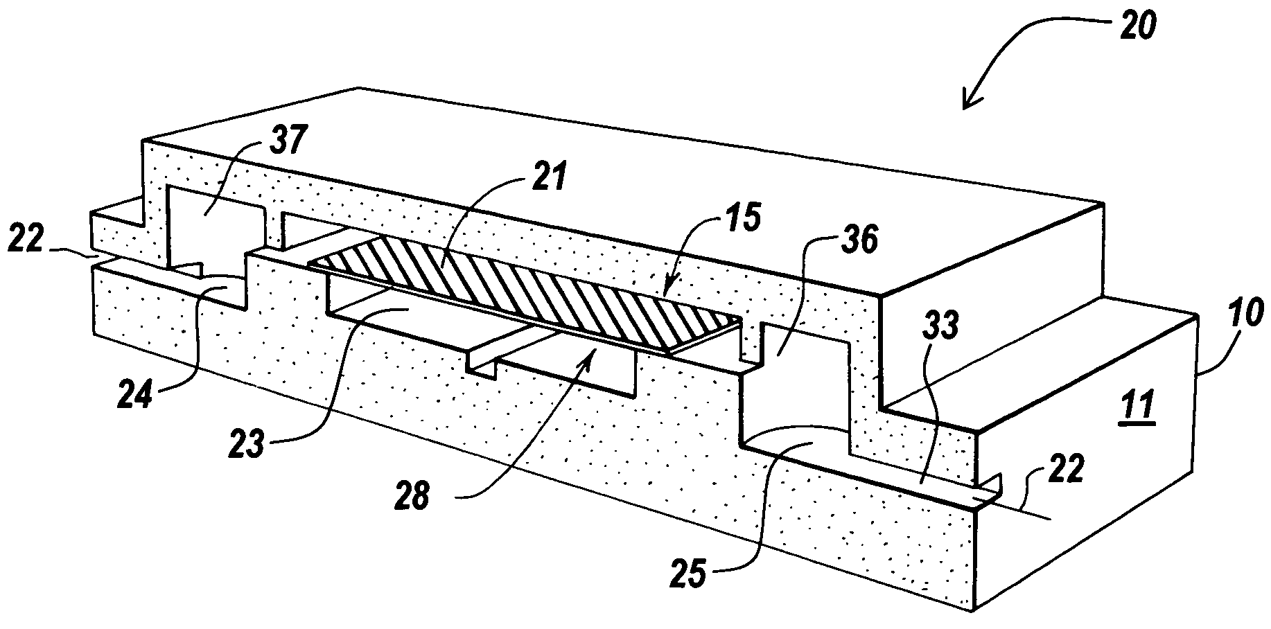
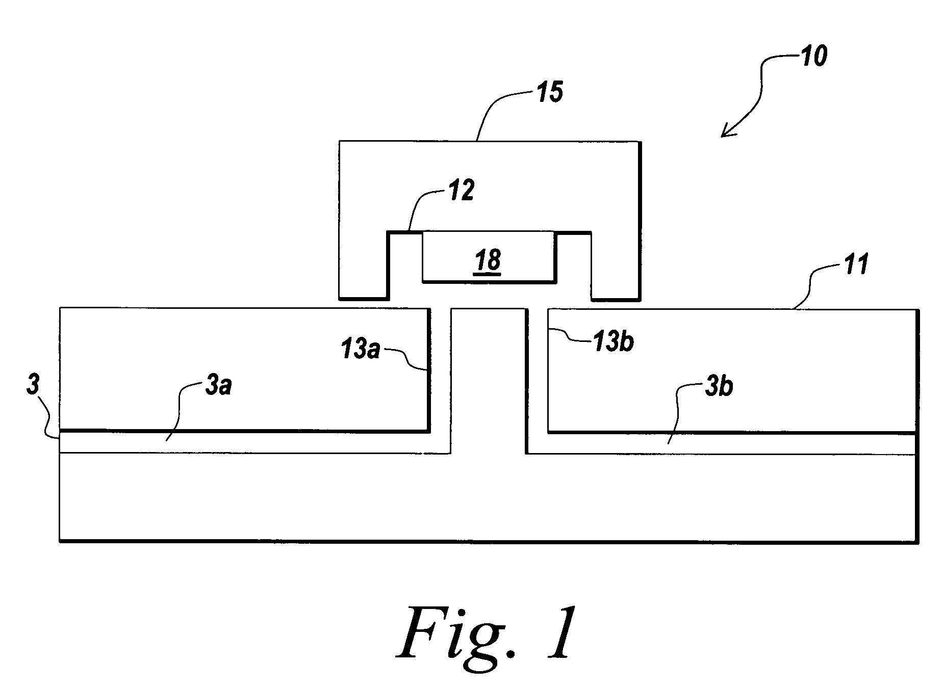
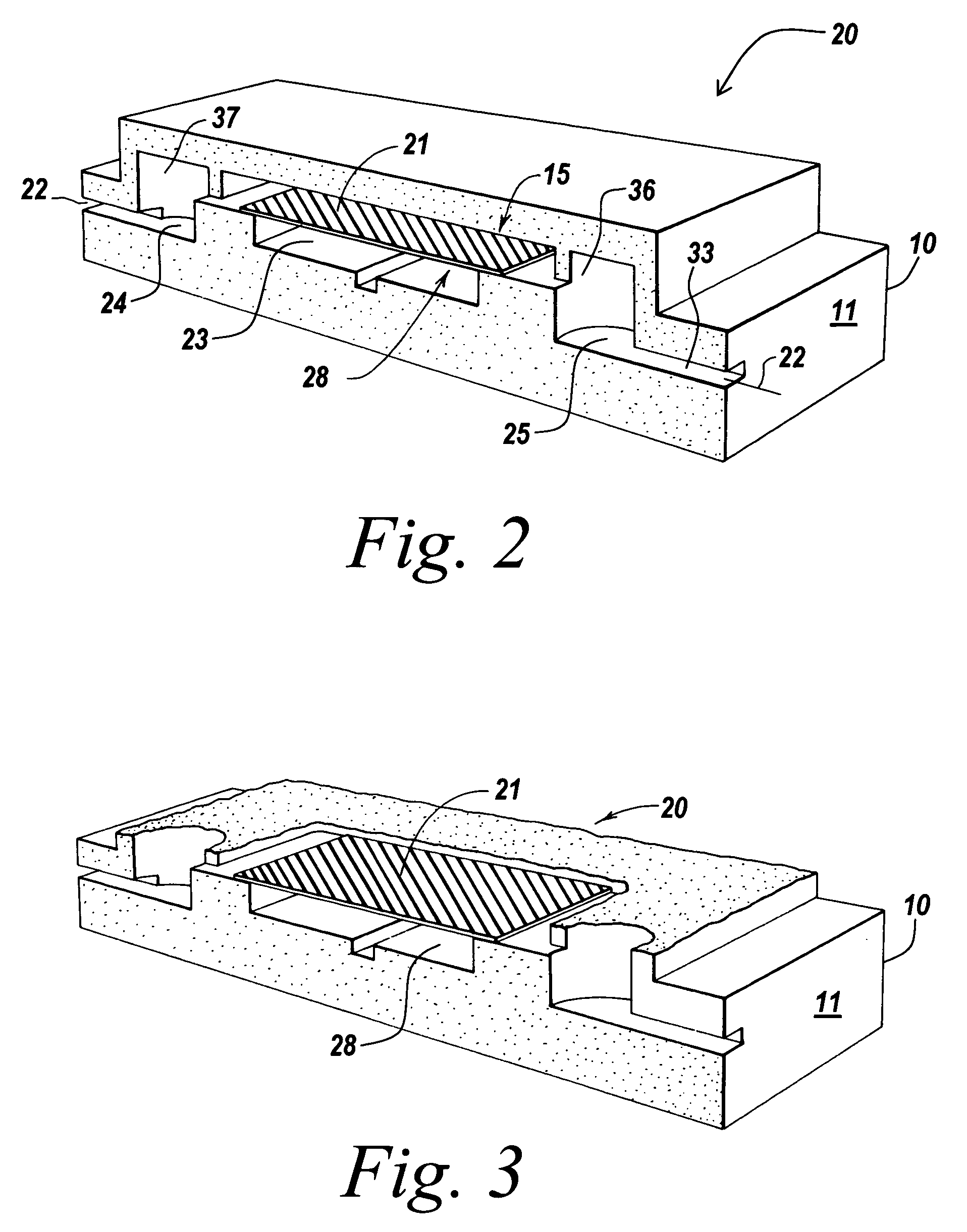
[0196]A plurality microfiltration devices with fluid channels, such as one of the devices shown in FIGS. 2–7B, were assembled on a chip. The microfiltration devices had a capacity of between about 1–2 μl to demonstrate the ability to set and reset buffers and small molecule concentrations in a flow stream containing proteins.

[0197]To demonstrate the diffusion of small molecules across the filter membranes of the microfiltration devices a mixture of 0.1 mM Fluorescein sodium salt (Sigma catalog #F6377) and 0.01 mM Rhodamine labeled BSA (Sigma catalog #A2289) in a phosphate buffered saline (PBS) pH 7.2 was passed through the channel on one side of each membrane and an accumulation of small molecules was detected on the other side. Flow through from the experimental step was monitored by collecting samples in micro well plates and recording excitation and emission spectra at 485 and 518 nm for Fluorescein sodium and at 544 and 590 nm for Rhodamine labeled BSA (RBSA). These results are ...

example 2

[0199]Glass chips with appropriate plumbing were designed and fabricated. To fabricate a fluidic circuit, channels in the glass chips were manufactured by chip microfabrication. The channels or plumbing were fabricated by etching channels in a glass plate followed by bonding of a second glass plate to enclose the channels, forming sealed microchannels. Vertical communication ports were laser machined in the glass to connect the channel to an exterior surface of the glass chip.

[0200]Capping modules were formed comprising plastic structures having a 3×5 mm planar cross section with a 6×0.04×1 mm channel formed in the base on the side that will be mounted towards the glass. The capping modules were prepared in arrays of 3×3 caps. Molecular fractionation devices were built by starting with a capping module array and sequentially bonding the following: a polyester bonding layer, a filter membrane layer, and another polyester bonding layer in a batch process to makes nine (a 3×3 array) mo...

example 2a

[0205]In a first example, the molecular fractionation device was preloaded with sample, followed by sub fraction elution using step gradient of elution buffer.

[0206]In the first example, the capping modules were prepared with matrix preloaded with sample. Protein A agarose beads were washed with ten times the volume of beads. A 1:1 ratio of antibody mixture and binding buffer was added to the prepared beads. 5 pt of this mixture was then loaded in the capping modules on the chips. As described above, there are two steps involved in the elution of sub fractions of samples. In a first step, the molecular fractionation device was washed with twenty times the volume of the capping module with a binding buffer to remove non specific binding by flowing binding buffer over the beads. In a second step, elution buffer with increasing concentration of elution buffer was used to elute sub fractions of trapped antibodies. Ten steps of concentration gradients were used with 20% increase in the e...


PUM

PropertyMeasurementUnit
volumeaaaaaaaaaa
volume capacityaaaaaaaaaa

Abstract

A system and method for integrating microfluidic components in a microfluidic system enables the microfluidic system to perform a selected microfluidic function. A capping module includes a microfluidic element for performing a microfluidic function. The capping module is stacked on a microfluidic substrate having microfluidic plumbing to incorporate the microfluidic function into the system. The microfluidic element may comprise a matrix having an affinity for selected molecules in a sample. The matrix binds, reacts with and / or retains the selected molecules without affecting other molecules in the sample.

Description

RELATED APPLICATIONS[0001]The present application is a continuation-in-part of U.S. patent application Ser. No. 10 / 329,018, filed Dec. 23, 2002, now U.S. Pat. No. 6,878,271 entitled “Implementation of Microfluidic Components in a Microfluidic System” and claims priority to U.S. Provisional Patent Application Ser. No. 60 / 459,028, filed Mar. 31, 2003, entitled “Molecular Fractionation Devices” and U.S. Provisional Patent Application Ser. No. 60 / 501,734, filed Sep. 9, 2003, entitled “Molecular Fractionation Devices”, the contents of which are herein incorporated by reference.FIELD OF THE INVENTION[0002]The present invention relates to a microfluidic system for handling fluid samples on a microfluidic level. More particularly, the present invention relates to a microfluidic system for separating or filtering particles, such as cells, in a suspension.BACKGROUND OF THE INVENTION[0003]Microfluidic devices and systems provide improved methods of performing chemical, biochemical and biologic...

Claims


Application Information

Patent Timeline
Patent Type & Authority Patents(United States)
IPC IPC(8): B01D63/00B01L11/00B01D57/00B01L99/00B31B1/60B65B1/00B65C1/00
CPCB01D63/087B01D67/0062B01L3/502707B01L3/502715B01L3/502738B01L3/502753C30B7/00B01D67/0034B01D63/088C30B29/58Y10T156/10B01L3/06B01L3/50273B01L2200/027B01L2200/028B01L2200/146B01L2300/041B01L2300/047B01L2300/0681B01L2300/0816B01L2300/0874B01L2400/0421B01L2400/0481B01L2400/0655B01L2400/0666C02F2209/36G01N27/44743G01N27/44773B01D2325/12Y10S977/786B01D2313/13B01D2313/40B01D2325/028
Inventor GILBERT, JOHN R.DESHPANDE, MANISHTRIKHA, JAISHREE
Owner CYTONOMEST
Why Eureka
Try Eureka