Flexible MEMS actuated controlled expansion stent

a microelectromechanical system and flexible technology, applied in the field of medical devices, can solve the problems of reduced blood flow, complex mechanism of balloon angioplasty, and inability to improve the coronary circulation, so as to minimize vascular tissue damage and restnosis, reduce vascular injury, and eliminate potential long-term complications

Inactive Publication Date: 2006-08-29
OKTAY HASAN SEMIH
View PDF4 Cites 169 Cited by
  • Summary
  • Abstract
  • Description
  • Claims
  • Application Information

AI Technical Summary

Benefits of technology

[0029]The present invention provides a medical device that includes structure and active motorized control mechanisms that are adapted to minimize vascular tissue damage and restenosis associated with traditional stenting techniques. The medical device includes structure that provides adequate initial scaffolding upon deployment and allows actively controlled expansion of the stent during deployment and over the lifetime of the medical device through a multiplicity of intermediate diameters to a fixed maximum diameter. For longer devices, the device will allow tapering of its diameter from proximal to distal end.
[0033]The exterior surface of the coiled shape memory or any metallic alloy employs a groove exactly opposite the gear rack on the interior surface of the shape memory alloy coiled material. The groove is of a reciprocal shape to the rack, which allows insertion of the rack into the groove when the shape memory or any metallic alloy is in the coiled state, and allows the rack to slide in the groove. The reciprocal shape of the groove prevents the rack from sliding out of the grove and maintains the overall tubular structure of the stent. The MEMS motor and gear assembly act to provide a mechanism to uncoil the shape memory or any metallic alloy, thus achieving radial expansion in a controlled manner. At least one pressure sensor is employed to detect forces applied to the vascular tissues. The sensor feeds the pressure information to a microchip which controls the force imparted to the gear by the MEMS motor.

Problems solved by technology

However, research has shown that the reduction of blood flow results from the combination of fixed vessel narrowing and abnormal vascular tone, contributed to by atherosclerosis induced endothelial cell dysfunction.
Non-invasive treatments cannot improve the coronary circulation when symptoms associated with coronary heart disease are severe.
Histological studies indicate, however, that the mechanisms of balloon angioplasty are much more complex and that the two primary mechanisms of this procedure are: (a) “over-stretching” of the vascular wall, which causes some mural injury, and (b) plaque fracture with partial separation from the vascular wall.
Nevertheless, it is assumed that excessive damage likely contributes to complications such as restenosis, dissection, vasospasm, and rupture.
Although this vascular wall damage results from mechanical forces, it is not known at which level of mechanical stress or strain it occurs.
The limitations of PTCA cited above resulted in the development of new technologies including atherectomy, laser angioplasty and coronary stenting.
The disadvantages of such devices include low radial stiffness and visibility, and difficulty in identifying a biocompatible polymer for use in coronary arteries.
Currently, none of the available stent designs incorporates all of these characteristics.
Although several clinical studies have demonstrated that coronary stenting (when compared with PTCA alone) reduces restenosis rates in selected atherosclerotic lesions, restenosis within the stent (in-stent restenosis) remains a clinical problem.
The incidence of in-stent restenosis has increased with recent advances in stent designs allowing stenting in difficult or less-than-ideal lesions, which leads to an intrinsically higher likelihood of restenosis following percutaneous intervention.
They undergo large deformations, relax when held at a constant strain, creep when subjected to a constant stress, and exhibit hysteresis when subjected to cyclic loading and unloading.
The determination of the failure characteristics of living tissues and organs is complex.
Since vessels usually experience only normal stresses (except near branch sites), they are not designed to resist this type of load and may therefore be susceptible to shear induced tearing.
The primary obstacle to the long-term success of PTCA and coronary stenting is restenosis.
Similarly, the treatment of a long, diffused lesion with PTCA would require inconsistent “over-stretching” between the normal and diseased segments of the target vessel and thus result in increased vascular damage.
These include directional, rotational and extractional atherectomy devices, excimer laser angioplasty and cutting balloon, but no therapy has consistently achieved reduction in restenosis.
There are associated problems such as edge restenosis, late thrombotic occlusions and potential delayed restenosis.
In addition, incorporating intracoronary radiation in daily clinical practice has practical problems.
The nature of both PTCA and / or stenting (with pre-dilatation) techniques is that they induce some degree of injury on the coronary artery wall via balloon dilatation.
Inherent in response to this injury, restenosis remains to be a major clinical problem.
Although, limiting the amount of injury during revascularization has been proposed as a means to limit the restenosis, there has been no attempt made to develop this idea further.

Method used


Image

  • Flexible MEMS actuated controlled expansion stent
  • Flexible MEMS actuated controlled expansion stent
  • Flexible MEMS actuated controlled expansion stent

Examples


Embodiment Construction

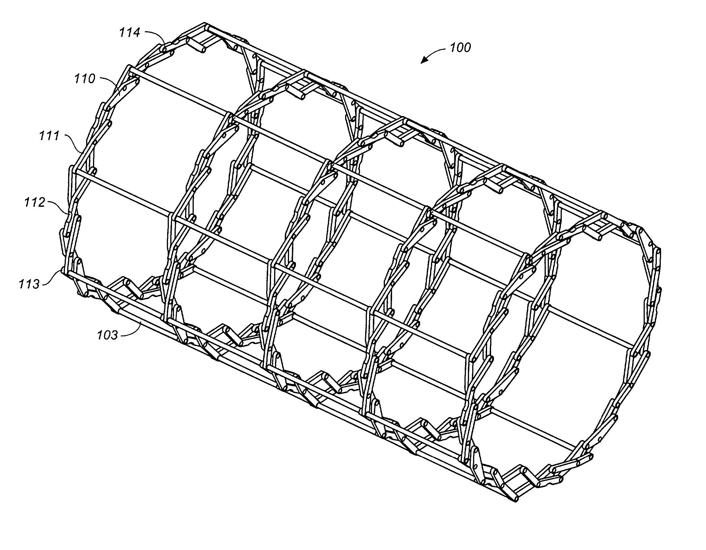
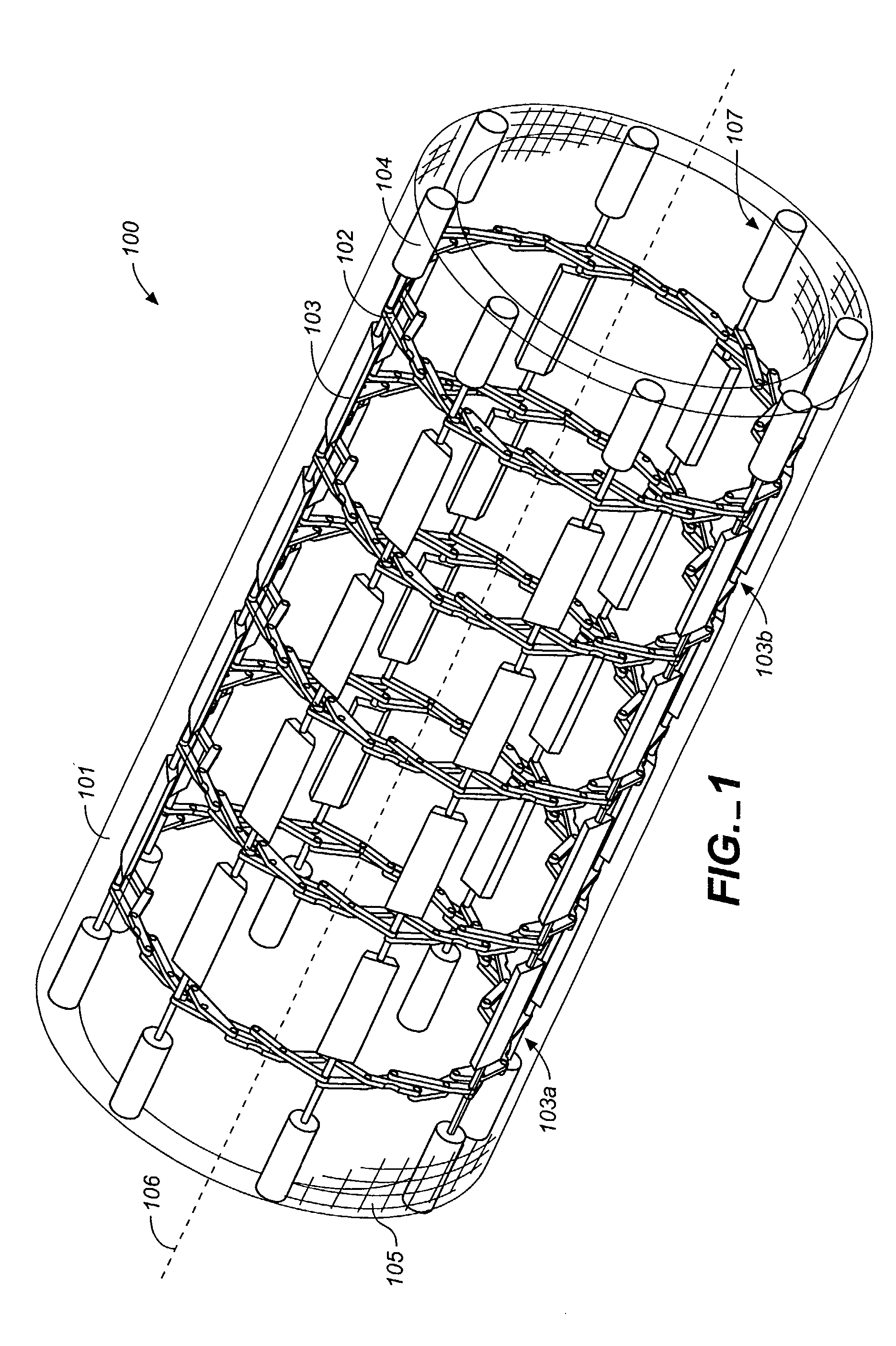
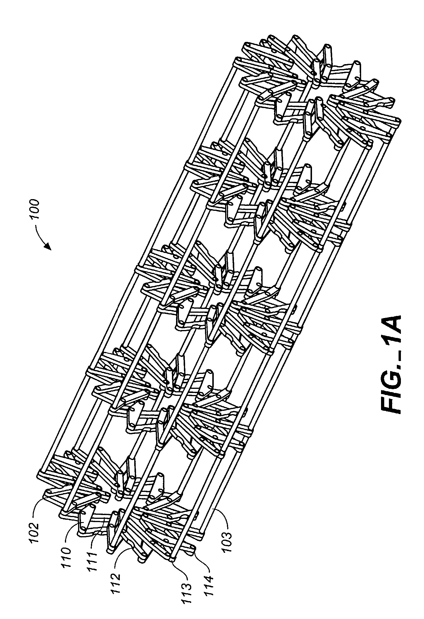
[0056]Referring to FIGS. 1 through 12, wherein like reference numerals refer to like components in the various views, FIG. 1 is a perspective view of the flexible MEM actuated controlled expansion stent of the present invention. The stent generally comprises a tubular body embodying structure that allows controlled radial expansion when the stent is deployed into vasculature. Specifically, the medical device includes physical and operational structure that enables it to be radially expanded in a controlled manner by the use of MEMS technology, providing optimal control of the expansion rate (gradual or step-wise) of the medical device and utilizing pressure or force sensors to evaluate the pressures / forces exerted on the vascular wall by the expansion, thus reducing injury to vascular tissue that lead to restenosis.

[0057]In its first preferred embodiment, the medical device of the present invention comprises a stent 100 having a stent body 101. The stent body is generally tubular in...


PUM


Abstract

An automatically controlled expansion stent having an expansible stent body, actuation means for expanding the stent body, and control means for actively controlling the actuation means. The stent body is substantially tubular and includes material layers covering a plurality of radial expansion trusses. The stent employs MEMS motors under the control of a programmable logic device to expand the trusses and the stent body. Force from the motor is communicated to the expansion trusses through interconnects, which pivotally connect the trusses and provide channels for pull wires extending from the motors to the trusses. The trusses comprise a plurality of hinged links which produce symmetrical expansion of the stent body when actuated by the MEMS motor.

Description

CROSS REFERENCE TO RELATED APPLICATIONS[0001]Not applicable.STATEMENT REGARDING FEDERALLY SPONSORED RESEARCH OR DEVELOPMENT[0002]Not applicable.REFERENCE TO A MICROFICHE APPENDIX[0003]Not applicable.TECHNICAL FIELD[0004]The present invention relates generally to a medical device, and more particularly to a flexible, Micro-Electro-Mechanical Systems (MEMS) actuated, automatically controlled expansion stent for improving the vascular / arterial luminal diameter and prevention of restenosis.BACKGROUND INFORMATION AND DISCUSSION OF RELATED ART[0005]Coronary artery disease (CAD) is the leading cause of death among men and women in the United States, accounting for approximately one of every five deaths. Approximately 2.4 million adults have a history of myocardial infarction (MI), angina, or both, and it is estimated that millions of others have clinically silent coronary artery disease.[0006]The traditional view has been that myocardial ischemia in CAD results from atherosclerotic plaques...

Claims


Application Information

Patent Timeline
Patent Type & Authority Patents(United States)
IPC IPC(8): A61F2/82A61F2/86A61F2/92
CPCA61F2/82A61F2/844A61F2/92A61F2/86A61F2230/005A61F2220/0075
Inventor OKTAY, HASAN SEMIH
Owner OKTAY HASAN SEMIH
Why Eureka
Try Eureka