Multi dynode device and hybrid detector apparatus for mass spectrometry

a detector and hybrid technology, applied in the field of hybrid detectors for mass spectrometry, can solve the problems of saturation of detectors, affecting the detection efficiency of ion detectors, and generating ghost peaks or artifacts in detected output, so as to avoid significant distortion or artifact generation of output signals, high peak signal output currents, and large dynamic range

Inactive Publication Date: 2006-09-12
AGILENT TECH INC
View PDF2 Cites 9 Cited by
  • Summary
  • Abstract
  • Description
  • Claims
  • Application Information

AI Technical Summary

Benefits of technology

[0018]The present invention provides an ion detector for use in mass spectrometry. The ion detector is a multi dynode device for electron multiplication and charged particle detection. In another embodiment, the ion detector is a hybrid detector comprising the multi dynode device (MDD) and an MCP. The hybrid electron multiplier detector has high peak signal output currents and large dynamic range while preserving the time-dependent information of the input event and avoiding the generation of significant distortions or artifacts on the output signal. The MDD of the present invention overcomes the above problems of the conventional hybrid detector by providing a unique EM portion, which avoids the path-length differences and maintains high peak current capability.
[0020]Electrons or ions entering the MDD at an input end or at a top end of the stack eventually strike one of the plates in the stack. The impact produces secondary electrons. The secondary electrons produced thereby are induced to move toward a bottom or an output end of the MDD under the influence of an electric field produced by bias voltages applied thereto via the power source. These secondary electrons either exit the MDD at its output end or impact another plate within the MDD producing additional secondary electrons. The power source of the MDD of the present invention comprises a voltage supply and a bias network. In the preferred embodiment, the bias network is a voltage divider. More preferably, the voltage divider is a capacitively loaded resistive voltage divider. Each dynode plate of the plurality is connected to a tap on the voltage divider. Thus, the MDD can supply high peak currents by virtue of the use of conductive plates and capacitively loaded bias circuitry.

Problems solved by technology

However, there is a practical limit to the detection gain of a given MCP 10.
This phenomenon results in saturation of the detector.
The backward motion known as “feedback” hurries the onset of saturation and can cause the creation of ghost peaks or artifacts in the detected output.
Unfortunately, even though the two MCPs 10, 21 of the Chevron configuration can be designed and biased independently, this type of hybrid detector 20 still suffers from relatively severe limitation in gain due to saturation, which limits the useful gain of this type of hybrid detector.
Further, the Chevron configuration has low dynamic range due to the inherently high resistance of the MCP plates.
The high resistance limits the secondary electron production once large numbers of electrons are present, which is particularly evident in and problematic for the second MCP 21.
Unfortunately, the DEM 24 has an inherent path-length difference for various ions and electrons.
The widening of the output signal pulse Δt and presence of spurious trailing pulses reduce the temporal resolution of the detector 25 and limits the useful dynamic range and resolution this type of hybrid detector 25.
Conventional electron multipliers (EMs) used for hybrid detectors, such as the classic DEM, are not optimized for this low Δt requirement.
While this venetian-blind style dynode provides high sensitivity and dynamic range, the DEM exhibits a rather large Δt.

Method used


Image

  • Multi dynode device and hybrid detector apparatus for mass spectrometry
  • Multi dynode device and hybrid detector apparatus for mass spectrometry
  • Multi dynode device and hybrid detector apparatus for mass spectrometry

Examples


Embodiment Construction

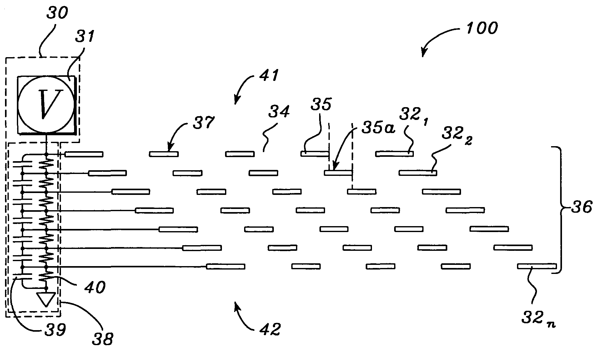
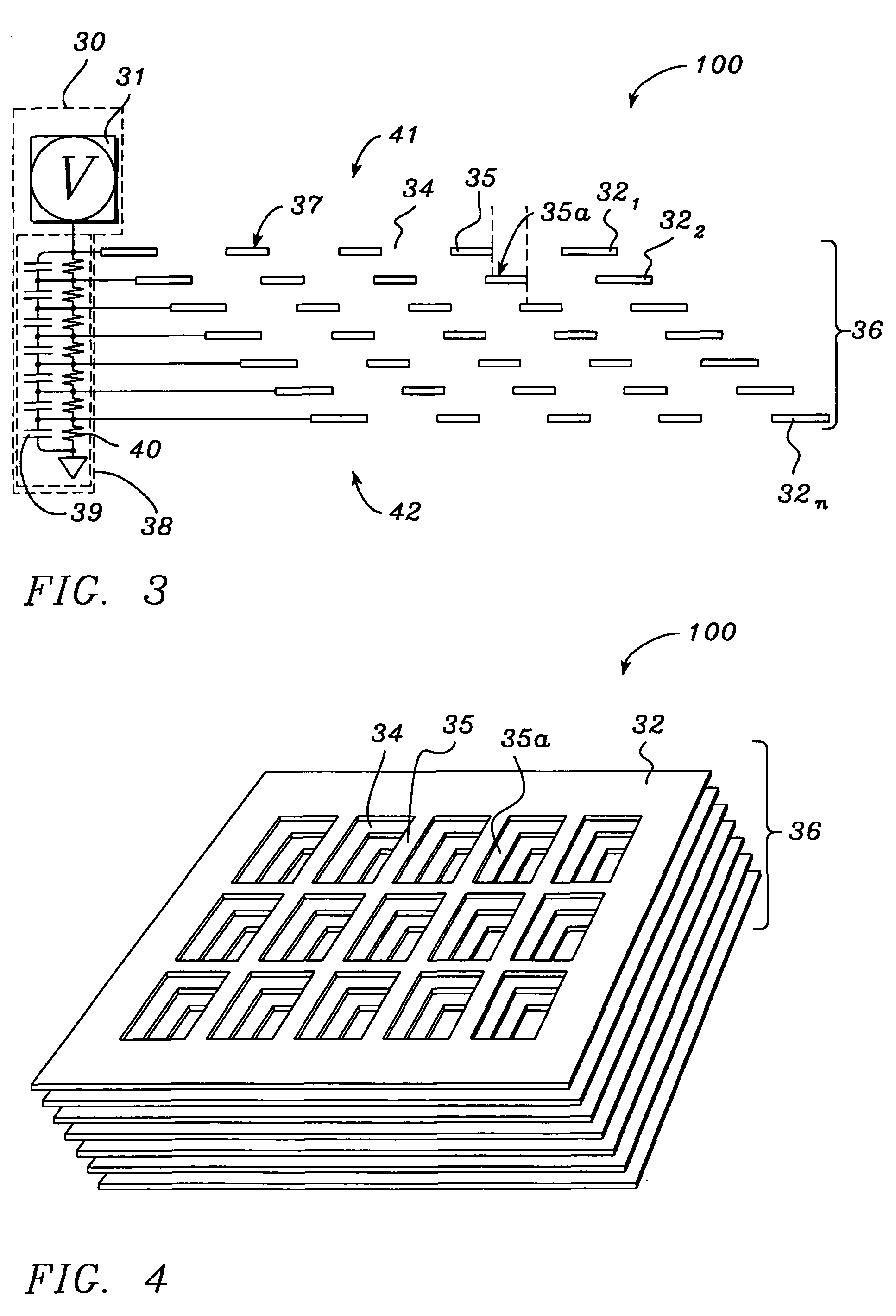
[0036]The multi dynode device (MDD) 100 of the present invention is illustrated in FIG. 3 in schematic form and in a perspective view in FIG. 4. The MDD 100 comprises a plurality of n conductive plates called dynode plates 32 arranged in a stack 36. Each dynode plate 32i, where i=1→n, has a plurality of apertures 34 formed therein. The dynode plates 32 in the stack 36 are spaced apart and laterally offset from one another. The MDD 100 further comprises a power source 30 comprising a bias network 38 and a bias voltage source 31. Bias voltages produced and supplied by the power source 30 are applied to each of the dynode plates 32i. The MDD 100 has an input end 41 for receiving ions or electrons and an output end 42 from which electrons exit the MDD 100. The input end 41 is sometimes referred to herein as the top 41 of the stack 36 of dynode plates 32 of the MDD 100 and the output end 42 is sometimes referred to herein as the bottom 42 of the stack 36 of dynode plates 32 of the MDD 10...


PUM


Abstract

A multi dynode device (MDD) for electron multiplication and detection and a hybrid detector using the MDD have high peak signal output currents and large dynamic range while preserving the time-dependent information of the input event and avoiding the generation of significant distortions or artifacts on the output signal. The MDD and hybrid detector overcome saturation problems observed in conventional hybrid detectors by providing a unique electron multiplier portion that avoids the path-length differences. The MDD and hybrid detector can be used in mass spectrometry, in particular, time-of-flight mass spectrometry. The MDD comprises a plurality of dynode plates arranged in a stacked configuration. Each dynode plate in the stack has a plurality of apertures for cascading secondary electrons through the stack. Each aperture comprises a mechanical bias or offset with respect to the apertures in adjacent plates. The offset is such that the electrons will impact with one or more of the dynode plates. The MDD further comprises a power source to provide a voltage bias to the dynode plates. The power source comprises a voltage supply and a voltage divider. Each dynode plate is connected to a tap on the voltage divider such that a voltage gradient is produced along the stack. The MDD can supply high peak currents. The hybrid detector comprises an input portion having a microchannel plate MCP and an output portion having the multi dynode device (MDD). The MCP and MDD are adjacent to one another. The MDD is planar, flat, and compact like that of the MCP, such that important temporal integrity of an input signal event is preserved.

Description

[0001]This is a divisional of application Ser. No. 09 / 541,209, filed on Apr. 3, 2000 now U.S. Pat. No. 6,617,768, the entire disclosure of which is incorporated herein by reference.TECHNICAL FIELD[0002]This invention relates to ion detectors for mass spectrometry. In particular, the invention relates to a hybrid electron multiplier detector for time of flight mass spectrometry.BACKGROUND ART[0003]Mass spectrometry is an analytical methodology often used for quantitative elemental analysis of materials and mixtures of materials. In mass spectrometry, a sample of a material to be analyzed called an analyte is broken into particles of its constituent parts. The particles are typically molecular in size. Once produced, the analyte particles (ions) are separated by the spectrometer based on their respective masses. The separated particles are then detected and a “mass spectrum” of the material is produced. The mass spectrum is analogous to a fingerprint of the sample material being analy...

Claims


Application Information

Patent Timeline
Patent Type & Authority Patents(United States)
IPC IPC(8): H01J49/26H01J43/22H01J49/02
CPCH01J49/025H01J43/246H01J43/22
Inventor HANSEN, STUART C.
Owner AGILENT TECH INC
Why Eureka
Try Eureka