Microfluidic chip with enhanced tip for stable electrospray ionization

a microfluidic chip and electrospray technology, applied in fluid speed measurement, isotope separation, particle separator tubes, etc., can solve the problems of high-stability spray, insufficient stability of chip edge surface, etc., and achieve the effect of being ready for manufactur

Inactive Publication Date: 2006-09-12
NORVIEL VERN
View PDF179 Cites 56 Cited by
  • Summary
  • Abstract
  • Description
  • Claims
  • Application Information

AI Technical Summary

Benefits of technology

[0010]The invention further provides single-use disposable microfluidic chips that are reliable, reproducible and easy-to-use. These microfluidic chips may be selected for sample separation and electrospray ionization processes utilizing electrospray emitters that are formed as an integral part of the chip. These embodiments of the invention reflect a chip design that provides an economical and effective solution that can be reproduced on a large scale production. Many microfluidic chips can be fabricated in batch quantities thus reducing the number of time-consuming steps in forming electrospray emitters and tips.
[0012]Another aspect of the invention provides methods of manufacturing microfluidic devices with separately formed ESI emitters. The microfluidic devices may be readily manufacturable following a mass production molding process. Many individual fluid devices may be fabricated at the same time using techniques similar to the manufacture of semiconductor chips for microprocessors. A metal-coated thin film polymer may be separately formed and bonded to polymer plates which are later separated into individual microfluidic devices by cutting apparatus. These and other embodiments of the invention provide convenient fabrication methods for economically manufacturing microfluidic devices for electrospray ionization applications.

Problems solved by technology

But the accompanying solvent is known to wet much of the edge surface of the chip so as not to offer a high-stability spray for many applications.
Other attempts to spray ionized particles directly from the edge of a microfluidic chip edge therefore rely on the formation of a hydrophobic surface that can yield improved spray results; however, even that often proves to be insufficiently stable.
While it is possible to generate a relatively stable ionization spray for mass spectrometric analysis with some of these microfluidic devices today, they generally require apparatus that is relatively impractical and economically unfeasible for mass production.

Method used


Image

  • Microfluidic chip with enhanced tip for stable electrospray ionization
  • Microfluidic chip with enhanced tip for stable electrospray ionization
  • Microfluidic chip with enhanced tip for stable electrospray ionization

Examples


Embodiment Construction

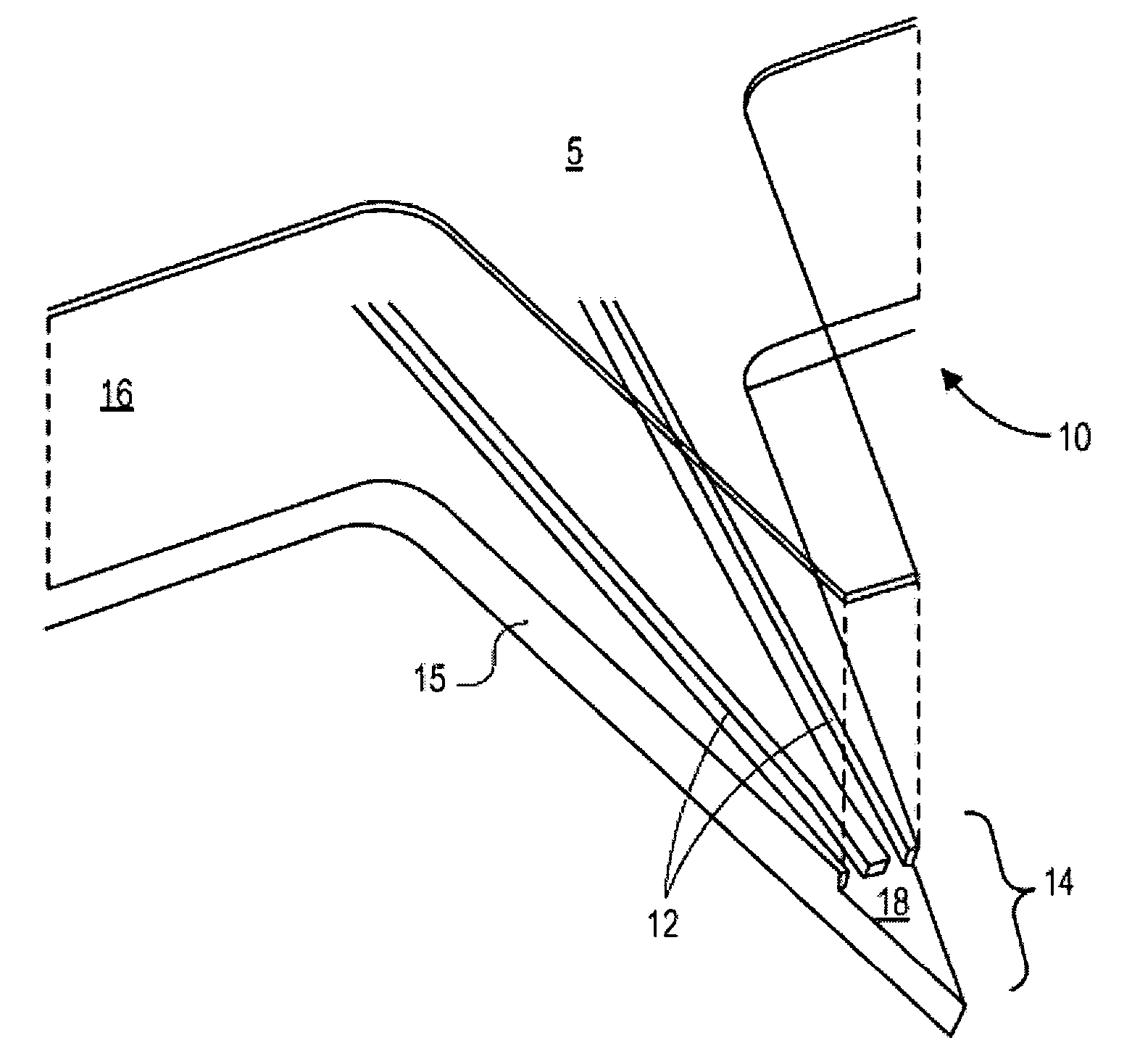
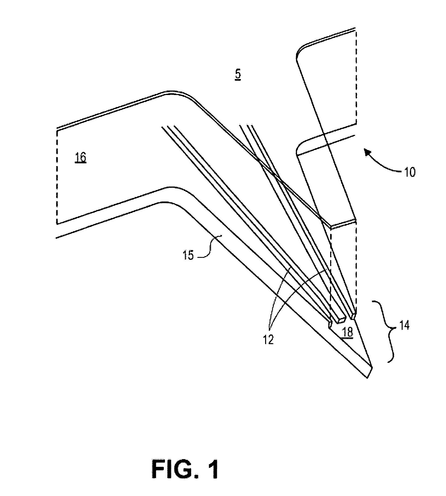
[0025]FIG. 1 illustrates a microfluidic chip 10 for electrospray ionization (ESI) applications that is formed with multiple fluid channels 12 converging at a distal tip region 14. The fluid channels 12 may be formed on a substrate layer 16 of the chip 10 that is composed of glass, quartz, ceramic, silicon, silica, silicon dioxide or other suitable material such as a polymer, copolymer, elastomer or a variety of commonly used plastics. The channels 12 can be created using a variety of methods, such as conventional semiconductor processing methods including photolithographically masked wet-etching and photolithographically masked plasma-etching, or other processing techniques including embossing, molding, injection molding, photoablating, micro-machining, laser cutting, milling, and die cutting. A variety of channel patterns and configurations may be also selected for the channels, including channels having a substantially rectangular, trapezoidal, triangular, or D-shaped cross-sectio...


PUM

PropertyMeasurementUnit
thicknessaaaaaaaaaa
electrical potentialaaaaaaaaaa
diameteraaaaaaaaaa

Abstract

A microfluidic chip formed with multiple fluid channels terminating at a tapered electrospray ionization tip for mass spectrometric analysis. The fluid channels may be formed onto a channel plate that are in fluid communication with corresponding reservoirs. The electrospray tip can be formed along a defined distal portion of the channel plate that can include a single or multiple tapered surfaces. The fluid channels may terminate at an open-tip region of the electrospray tip. A covering plate may substantially enclose most portions of the fluid channels formed on the channel plate except for the open-tip region. Another aspect of the invention provides methods for conducting mass spectrometric analysis of multiple samples flowing through individual fluid channels in a single microfluidic chip that is formed with a tapered electrospray tip having an open-tip region.

Description

CROSS-REFERENCE[0001]This patent application is a continuation-in-part application of U.S. application Ser. No. 10 / 649,350 filed Aug. 26, 2003, now U.S. Pat. No. 6,803,568, entitled “Multi-Channel Microfluidic Chip for Electrospray Ionization” which is herein incorporated by reference in its entirety.FIELD OF THE INVENTION[0002]The invention relates to microfluidic chips for electrospray ionization applications. More particularly, the invention relates to improved electrospray ionization tips for mass spectrometric analysis.BACKGROUND OF THE INVENTION[0003]Electrospray ionization is used to produce ions for mass spectrometry analysis including ions that are derived from relatively large complex molecules such as proteins and nucleic acid molecules. During the electrospray ionization procedure, a sample solution is exposed to an electrical field that charges the surface of the liquid and emerges from an electrospray tip or needle. A spray of finely dispersed charged droplets is there...

Claims


Application Information

Patent Timeline
Patent Type & Authority Patents(United States)
IPC IPC(8): H01J49/04B01D59/44H03H19/00B01L3/00B01L3/02B81B1/00G01D5/20G01NG01N27/447
CPCB01L3/0268B01L3/502715H01J49/0018B81B1/008G01N27/44717H01J49/167B01L2300/0816B01L2300/0867B01L2300/0887B81B2201/058B01L2400/027
Inventor ZHAO, MINGQIBLAGA, IULIUBOUSSE, LUCSTULTS, JOHNNI, JING
Owner NORVIEL VERN
Why Eureka
Try Eureka