Raman spectroscopy system and method and specimen holder therefor

a raman and spectroscopy technology, applied in the field of raman spectroscopy, can solve the problems of reducing the sensitivity and hence material selectivity, affecting the raman signature of specimens, and not sufficiently developing the mathematical techniques of vibrational analysis to permit the extension of these differential studies, so as to reduce the contamination of the specimen's raman signature and reduce the cross section of raman.

Active Publication Date: 2006-09-19
AHURA CORP
View PDF2 Cites 29 Cited by
  • Summary
  • Abstract
  • Description
  • Claims
  • Application Information

AI Technical Summary

Benefits of technology

[0027]Accordingly, an object of the invention is to produce a Raman spectroscopy system and method including an optical probe assembly which exhibits a low Raman cross section therein, to reduce contamination of the specimen's Raman signature with the background signal generated by the probe.
[0028]A further object of the invention is to provide a Raman spectroscopy system in which the optical probe assembly is compact, flexible, and rugged.
[0029]A still further object of the invention is to provide a specimen holder and method which eliminates the problems associated with the inherent Raman signature of the material of specimen holders.

Problems solved by technology

Physical chemists have made extremely effective use of such comparisons in the elucidation of the finer structural details of small symmetrical molecules, such as methane and benzene, but the mathematical techniques of vibrational analysis are not yet sufficiently developed to permit the extension of these differential studies to the Raman and infrared spectra of the more complex molecules that constitute the main body of both organic and inorganic chemistry.
A persistent problem in the design of such systems is the delivery and collection of laser light and the Raman signature from the specimen.
However, the high intensity of optical power and the non-linear coefficients of the optical fiber's refractive index cause the generation of a background Raman signal.
The result is a decrease in sensitivity and hence material selectivity.
Another persistent problem with Raman spectroscopy is the interference of the inherent Raman signature of the typical glass vial in which the specimen is contained with the Raman signature of the specimen being tested.

Method used


Image

  • Raman spectroscopy system and method and specimen holder therefor
  • Raman spectroscopy system and method and specimen holder therefor
  • Raman spectroscopy system and method and specimen holder therefor

Examples


Embodiment Construction

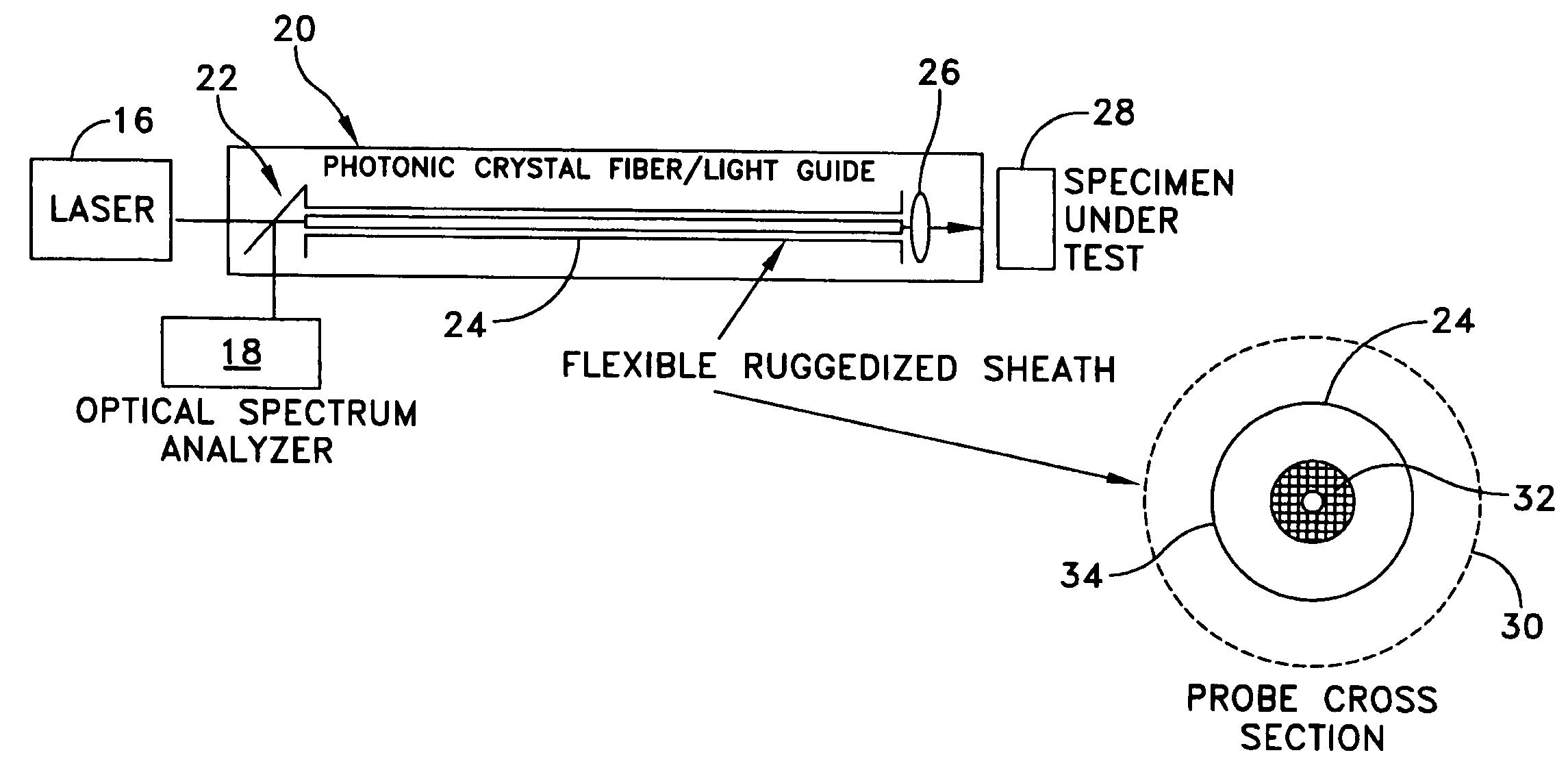
[0050]The improved Raman spectroscopy system (FIG. 5) includes an optical probe assembly 20 which comprises a dichroic beam splitter / demultiplexer 22, a single hollow-core photonic bandgap fiber / light guide 24, and a lens coupling unit 26.

[0051]The dichroic beam splitter / demultiplexer 22 is used to spatially separate the reflected lasing signal from the specimen's Raman signature.

[0052]The photonic bandgap fiber / light guide 24 allows the copropagation of the high intensity laser light with the Stokes shifted Raman signature from a specimen 28, while introducing little background Raman onto the collected signature. This fiber / light guide 24 can be placed in a ruggedized sheath 30 for environmental protection. The photonic bandgap fiber / light guide 24 exhibits a low Raman cross section inasmuch as a large fraction of the optical power is located in the air filled hollow core 32 or in air filled holes of the fiber cladding (not shown). The core 32 preferably is encased in a glass cladd...


PUM

PropertyMeasurementUnit
Raman spectroscopyaaaaaaaaaa
optical spectrum analyzeraaaaaaaaaa
Ramanaaaaaaaaaa

Abstract

A Raman spectroscopy system includes a laser source for providing a laser beam, and an optical probe assembly including a photonic crystal fiber light guide for receiving the laser beam from the laser source and for directing the laser beam toward a specimen of selected material, a lens for receiving the laser beam in the light guide and directing the beam onto the specimen and for receiving reflected light from the specimen and directing the reflected light back through the fiber light guide, and a dichroic beam splitter for directing a portion of the reflected beam out of the optical probe assembly. The system further includes an optical spectrum analyzer for receiving the portion of the reflected beam and for exhibiting a Raman signature of the specimen.

Description

REFERENCE TO PENDING PRIOR PATENT APPLICATIONS[0001]This patent application claims benefit of:[0002](1) pending prior U.S. Provisional Patent Application Ser. No. 60 / 463,967, filed Apr. 18, 2003 by Kevin J. Knopp et al. for SAMPLE VIAL FOR RAMAN SPECTROSCOPY WHICH ENABLES IMPROVED SPECIMEN SELECTIVITY; and[0003](2) pending prior U.S. Provisional Patent Application Ser. No. 60 / 517,811, filed Nov. 6, 2003 by Kevin J. Knopp et al. for OPTICAL PROBE WITH LOW RAMAN CROSS SECTION.[0004]The two above-identified patent applications are hereby incorporated herein by reference.BACKGROUND OF THE INVENTION[0005]1. Field of the Invention[0006]This invention relates to Raman spectroscopy and is directed more particularly to a Raman spectroscopy system and method including an improved optical probe assembly, and an improved specimen holder for retaining a specimen for examination by a Raman spectroscopy system.[0007]2. Description of the Prior Art[0008]Raman spectroscopy is based upon the Raman ef...

Claims


Application Information

Patent Timeline
Patent Type & Authority Patents(United States)
IPC IPC(8): G01J3/44G01N21/03G01N21/65
CPCG01N21/65G01J3/44
Inventor KNOPP, KEVIN J.VAKHSHOORI, DARYOOSH
Owner AHURA CORP
Why Eureka
Try Eureka