
Liquid crystal alignment layer

Inactive Publication Date: 2006-10-10
UNIVERSITY OF HULL
View PDF25 Cites 18 Cited by
  • Summary
  • Abstract
  • Description
  • Claims
  • Application Information

AI Technical Summary

Benefits of technology

[0006]Conventional liquid crystal displays (LCD) comprise a liquid crystal alignment layer for aligning the liquid crystal. The alignment layer is typically made of an electrical insulator. Light emitting displays (e.g. made by the in situ polymerization of reactive mesogens) also require alignment such as by the use of aligning materials (e.g. polyimide) which, if as is usual, are insulating can impair the efficiency of the device. The Applicants have now found that a number of benefits may be achieved by enhancing the electrical conductivity of the alignment layer by the inclusion of a transport material therein.
[0007]In one aspect, enhancing the electrical conductivity of the alignment layer can reduce adverse residual dc effects in liquid crystal display cells. These arise as a result of poorly balanced dc drive schemes that leave a small charge in the cell, which can induce image sticking e.g. in active matrix-addressed LCDs. The adverse effects are more frequently observed in ferroelectric liquid crystal (FLC) cells where dc imbalance is more likely to occur. The presence of a conducting alignment layer enables residual dc to discharge, thereby reducing the adverse affects.
[0008]In another aspect, in FLC cells the switching of the spontaneous polarisation charge produces significant charge within the cell. This charge tends to counter the effect of any electric field applied to align the liquid crystal molecules therein and thereby adversely reduce or eliminate any bistability in the display cell. The presence of a conducting alignment layer tends to reduce this adverse effect.

Problems solved by technology

Light emitting displays (e.g. made by the in situ polymerization of reactive mesogens) also require alignment such as by the use of aligning materials (e.g. polyimide) which, if as is usual, are insulating can impair the efficiency of the device.
These arise as a result of poorly balanced dc drive schemes that leave a small charge in the cell, which can induce image sticking e.g. in active matrix-addressed LCDs.
This charge tends to counter the effect of any electric field applied to align the liquid crystal molecules therein and thereby adversely reduce or eliminate any bistability in the display cell.

Method used


Image

  • Liquid crystal alignment layer
  • Liquid crystal alignment layer
  • Liquid crystal alignment layer

Examples


Embodiment Construction

General Experimental Details

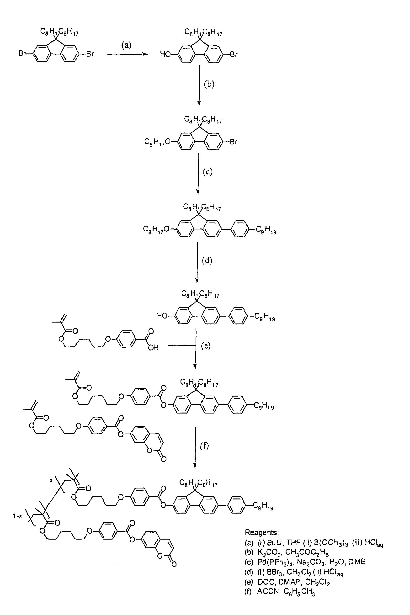
[0144]Fluorene, 2-(tributylstanyl)thiophene, 4-(methoxyphenyl)boronic acid and the dienes were purchased from Aldrich and used as received. Reagent grade solvents were dried and purified as follows. N,N-Dimethylformamide (DMF) was dried over anhydrous P2O5 and purified by distillation. Butanone and methanol were distilled and stored over 5 Å molecular sieves. Triethylamine was distilled over potassium hydroxide pellets and then stored over 5 Å molecular sieves. Dichloromethane was dried by distillation over phosphorus pentoxide and then stored over 5 Å molecular sieves. Chloroform was alumina-filtered to remove any residual ethanol and then stored over 5 Å molecular sieves. 1H nuclear magnetic resonance (NMR) spectra were obtained using a JOEL JMN-GX270 FT nuclear resonance spectrometer. Infra-red (IR) spectra were recorded using a Perkin Elmer 783 infra-red spectrophotometer. Mass spectral data were obtained using a Finnegan MAT 1020 automated GC / MS. The...


PUM

PropertyMeasurementUnit
Thicknessaaaaaaaaaa
Transport propertiesaaaaaaaaaa
Emissivityaaaaaaaaaa

Abstract

There is provided a liquid crystal alignment layer comprising an alignment layer; and chemically bound to said alignment layer, a transport material. Also provided are methods for forming the liquid crystal alignment layer and the use thereof in displays for electronic apparatus.

Description

[0001]This application is a continuation-in-part of Ser. No. 09 / 898,749 filed Jul. 3, 2001 now abandoned and claims priority from GB Application No. 0115987.0 filed Jun. 29, 2001.BACKGROUND OF THE INVENTION[0002]1. Field of the Invention[0003]The present invention relates to a liquid crystal alignment layer suitable for use in displays for electronic products and a method of forming the liquid crystal alignment layer and displays.[0004]2. Prior Art[0005]Modern consumer electronics require cheap, high-contrast displays with good power efficiency and low drive voltages. Particular applications include displays for mobile phones and hand-held computers. Liquid crystal displays are often used for this purpose and light emitting polymers displays are also of interest for this purpose.SUMMARY OF THE INVENTION[0006]Conventional liquid crystal displays (LCD) comprise a liquid crystal alignment layer for aligning the liquid crystal. The alignment layer is typically made of an electrical insu...

Claims


Application Information

Patent Timeline
IPC IPC(8): H05B33/00C09K19/56C09K19/32C09K19/34C09K19/38C09K19/40G02F1/13357G02F1/1337G02F1/141
CPCC09K19/32C09K19/3497C09K19/3861C09K19/408G02F1/133711C09K19/3402Y10T428/1055C09K2019/3425G02F1/133603G02F1/133788G02F1/141G02F2001/133726G02F2001/133796H01L51/5293Y10S428/917Y10T428/1014Y10T428/1005Y10T428/1023C09K2323/023C09K2323/04C09K2323/027C09K2323/02G02F1/133726G02F1/133796H10K50/868
Inventor O'NEILL, MARYKELLY, STEPHEN MALCOLMCONTORET, ADAM EDWARD ALEXANDERRICHARDS, GARY JAMESCOATES, DAVID
Owner UNIVERSITY OF HULL
Learn More