Power cogeneration system and apparatus means for improved high thermal efficiencies and ultra-low emissions

a power cogeneration system and ultra-low emission technology, applied in the direction of machines/engines, jet propulsion plants, hot gas positive displacement engine plants, etc., can solve the problems of reducing the application of oxy-fuel combustion in the present energy conversion facility, unable to reach a consensus as to precisely, and unable to meet the needs of scientific community, so as to achieve maximum thermal efficiency, reduce the effect of “greenhouse gas” and enhance the simple-cycle operating thermal efficiency

Inactive Publication Date: 2006-10-24
AES DEV CO
View PDF15 Cites 172 Cited by
  • Summary
  • Abstract
  • Description
  • Claims
  • Application Information

AI Technical Summary

Benefits of technology

[0013]The present invention describes the means by which the cited partially-open AES turbine cycle system and apparatus can be incorporated into a simplified and improved gas turbine cogeneration system having simplified apparatus means and that can further achieve increased turbine cogeneration system thermal efficiencies which can exceed 115%.
[0066](a) The oxy-fuel combustion chamber assembly's low operating pressures reduces the work (per pound of primary re-pressurized recycled gas) that is adsorbed by the turbine train's compressor section that re-pressurizes the recycled gas stream that becomes the downstream highly superheated working motive fluid that is expanded through the hot gas expansion turbine assembly;

Problems solved by technology

The best available applied turbine low NO.sub.x combustion technology for limiting gas turbine NO.sub.x emissions, using stiochiometric air / fuel primary combustion reaction chemistry means, still results in the production of NO.sub.x and CO that are no longer acceptable for new power or energy conversion facilities in numerous states and metropolitan environmental compliance jurisdictions.
Due to the high temperatures and speed of completed fuel combustion, the scientific community has been unable to reach a consensus as to precisely what series of altered chemical reactions occur when water vapor and / or carbon dioxide is introduced into a turbine combustion chamber.
Both the present air separation art methods' high energy costs of producing acceptable combustion grade oxygen, and the lack of devised combustion system methods to control preset desired oxy-fuel combustion heater-burner or combustion chamber uniform maximum temperatures, have curtailed oxy-fuel combustion applications within present energy conversion facilities.

Method used


Image

  • Power cogeneration system and apparatus means for improved high thermal efficiencies and ultra-low emissions
  • Power cogeneration system and apparatus means for improved high thermal efficiencies and ultra-low emissions
  • Power cogeneration system and apparatus means for improved high thermal efficiencies and ultra-low emissions

Examples


Embodiment Construction

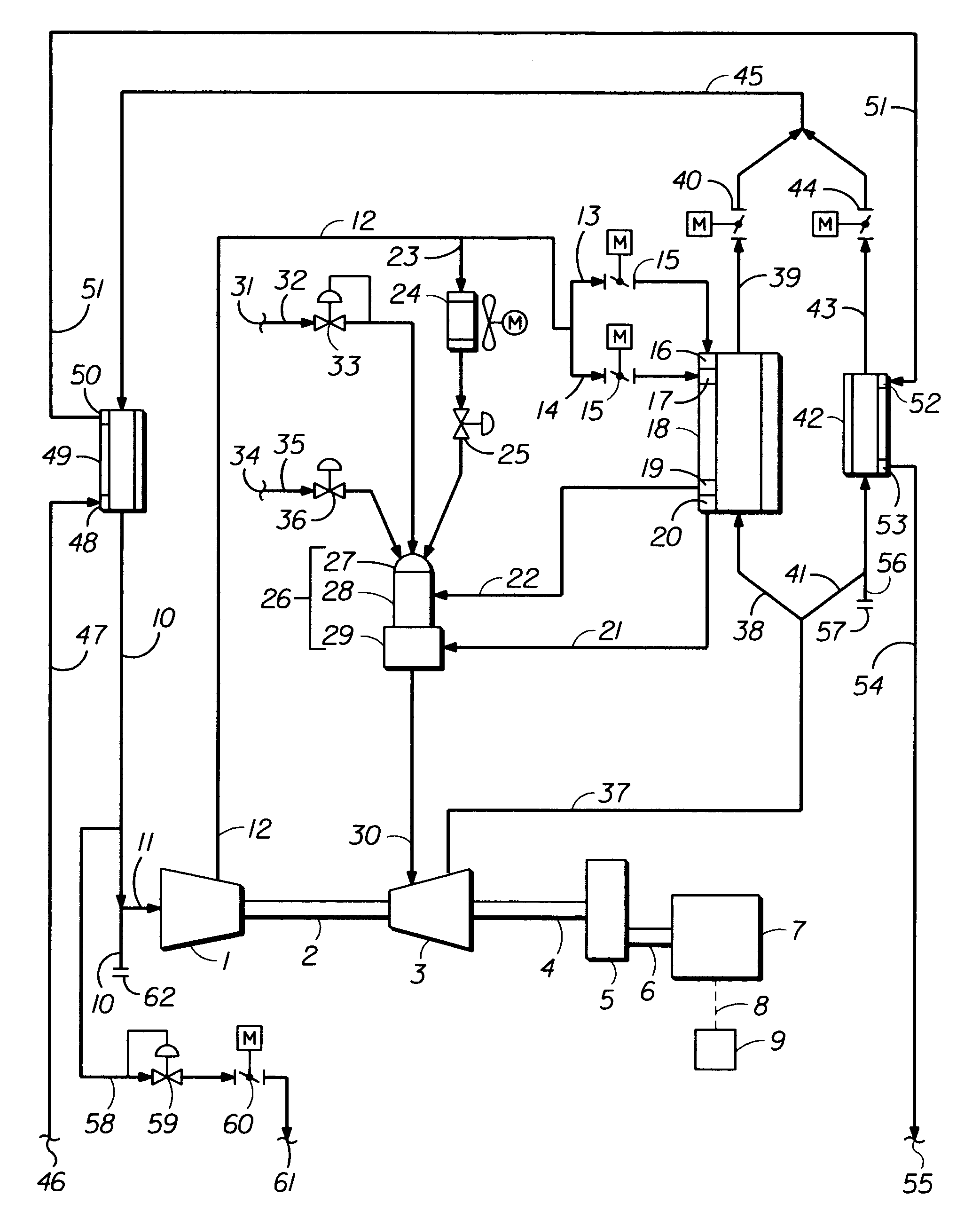
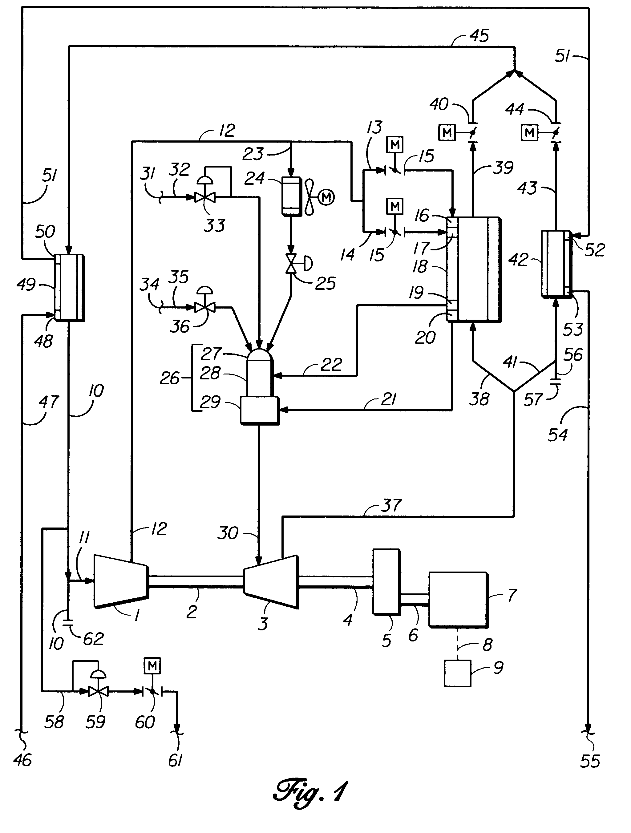
[0075]Referring now more particularly to FIG. 1, a modified current art gas turbine's exhaust recycle gas compressor section 1 comprises two or more recycled exhaust gas compression stages, positioned in series, with a final stage of radially directed discharge flow of compressed recycle exhaust gas. In the case of a two-shaft turbine, the power to drive the recycle compressor section 1 is transmitted by shaft 2, on which one or more high-pressure power extraction turbine stages are mounted within the hot gas expander power turbine assembly 3. The second shaft, designed for mechanical equipment or generator drive applications, has one or more low-pressure hot gas expansion stages mounted on power output shaft 4, with coupling means (not shown) for power transmission to rotate the driven equipment.

[0076]The invention's cycle adaptation to current art gas turbine driven mechanical equipment may or may not require the addition of a gearbox or variable speed coupling 5 to adapt the spee...


PUM


Abstract

A power cogeneration system employing a partially-open gaseous fluid cycle method and apparatus devices for oxy-fuel combustion conversion of a given hydrocarbon composition fuel's heat-value energy into mechanical or electrical power energy, and transferred useful heat energy, with accompanying large reductions of consumed fuel and undesirable exhaust emissions.

Description

BACKGROUND OF THE INVENTION[0001]When Brayton Simple Cycle gas turbines operate as mechanical power drive sources to electric generators and other mechanically driven devices, atmospheric air is compressed and mixed with hydrocarbon gases or atomized hydrocarbon liquids for the resulting mixture's ignition and combustion at constant pressure. To produce power, the hot combustion and working motive fluid gases are expanded to near atmospheric pressure across one or more power extraction turbine wheels, positioned in series.[0002]The majority of Brayton simple open-cycle aero-derivative-style low nitrogen oxide emission (that may hereafter be referred to as Low-NO.sub.x) current art gas turbines are predominantly presently limited in achieving shaft output horsepower rating with 26% to 39% thermal efficiencies, whereas most simple cycle industrial-style Low-NO.sub.x art gas turbines are predominantly presently limited in achieving shaft output horsepower rating with 27% to 34% thermal...

Claims


Application Information

Patent Timeline
Patent Type & Authority Patents(United States)
IPC IPC(8): F02C3/34F02C6/06F02C6/04
CPCF02C6/04Y02E20/14
Inventor NEARY, DAVID
Owner AES DEV CO
Why Eureka
Try Eureka