
Perpendicular magnetic recording media and magnetic storage

a magnetic recording media and perpendicular magnetic technology, applied in data recording, nanomagnetism, instruments, etc., can solve the problems of insufficient magnetic properties, difficult to thin the intermediate layer, and difficult to obtain sufficient magnetic properties, so as to reduce the noise of the transition noise originated in the effect of small saturation magnetic flux density and reducing the noise of the soft magnetic underlayer

Inactive Publication Date: 2006-11-21
HITACHI LTD
View PDF23 Cites 1 Cited by
  • Summary
  • Abstract
  • Description
  • Claims
  • Application Information

AI Technical Summary

Benefits of technology

The patent text describes a method for reducing noise in a perpendicular magnetic recording medium by using a non-magnetic amorphous alloy as the intermediate layer between the soft magnetic underlayer and the perpendicular magnetic recording layer. This alloy helps to improve the perpendicular orientation of the recording layer and to cut off the influence of the soft magnetic underlayer on the recording layer. The use of this alloy also results in a thinner intermediate layer, which increases recording and reproduction efficiency. Additionally, the patent text discusses the use of ferromagnetic nano-crystals precipitated by annealing to further reduce noise in the recording layer. Overall, this method improves the performance of perpendicular magnetic recording media.

Problems solved by technology

When the present inventors considered applying such non-magnetic underlayer materials for the intermediate layer of the double layer perpendicular magnetic recording medium, various problems have become clear.
For example, when Ti is used for the intermediate layer, although it shows a relatively good property on the amorphous soft magnetic underlayer, the c-axis vertical orientation of the perpendicular magnetic recording layer is degraded on the poly-crystalline soft magnetic underlayer, there is seen a tendency that a sufficient magnetic property cannot be obtained.
However, for example, when the amorphous material such as Ge is used for the intermediate layer, it is difficult to make the intermediate layer thin because diffusion easily occurs at the interface.

Method used


Image

  • Perpendicular magnetic recording media and magnetic storage
  • Perpendicular magnetic recording media and magnetic storage
  • Perpendicular magnetic recording media and magnetic storage

Examples


embodiment 1

[Embodiment 1]

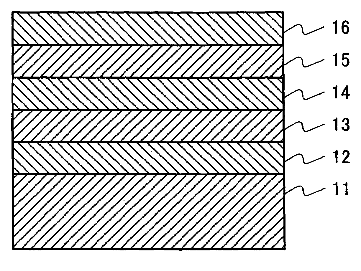
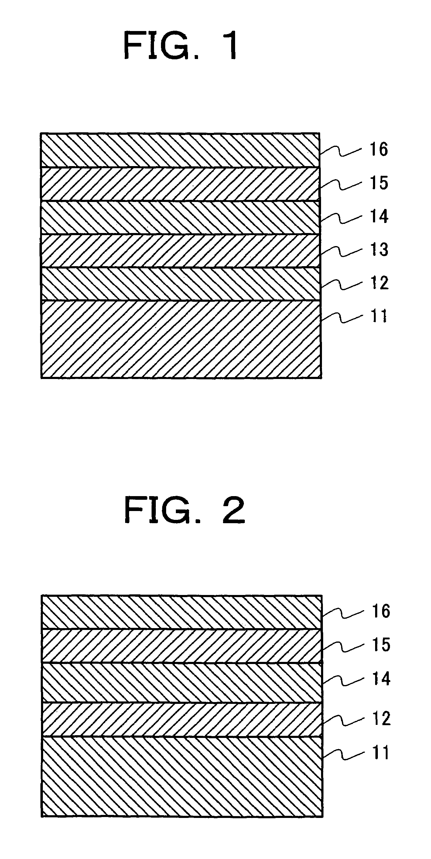
[0029]FIG. 1 shows a layer constitution of a magnetic recording medium of the present embodiment. A glass substrate, to which an alkaline cleaning was performed, having a diameter of 2.5 inches was used as a substrate 11, and a soft magnetic underlayer 12, an intermediate layer 13, a perpendicular recording layer 14 and a protective layer 15 were sequentially formed by DC magnetron sputtering method.

[0030]An Fe-8 at % Ta-12 at % C target for the soft magnetic underlayer 12; a Ni-37.5 at % Ta-10 at % Zr target for the intermediate layer 13; a Co-22 at % Cr-10 at % Pt target, a Co-22 at % Cr-12 at % Pt target and a Co-22 at % Cr-14 at % Pt target for the perpendicular recording layer 14; and a carbon target for the protective layer 15 were used respectively. Film forming was performed under the conditions that an Ar gas pressure was set at 0.5 Pa, the soft magnetic underlayer 12 was formed, and then annealing by an infrared lamp heater at 1600 w for 12 s was performed (a...

embodiment 2

[Embodiment 2]

[0043]In a layer constitution similar to the embodiment 1 (refer to FIG. 1), the intermediate layer 13 was formed and then exposed to a mixed gas atmosphere of 99% Ar-1% O2 (0.36 Pa to 3.6 Pa) for 5 seconds. Thereafter, the perpendicular magnetic recording layer 14 and the protective layer 15 were sequentially formed by the DC magnetron sputtering method. The Fe-8 at % Ta-12 at % C target for the soft magnetic underlayer 12; the Ni-37.5 at % Ta-10 at % Zr target for the intermediate layer 13; the Co-22 at % Cr-14 at % Pt target for the perpendicular magnetic recording layer 14; and the carbon target for the protective layer 15 were used respectively. The film forming conditions and the film thickness of each layer are similar to the embodiment 1 except that the thickness of the intermediate layer is fixed at 5 nm.

[0044]The recording-reproduction property of the medium of the present embodiment was evaluated under the conditions similar to the embodiment 1 (the ring hea...

embodiment 3

[Embodiment 3]

[0048]In a layer constitution similar to the embodiment 1 (refer to FIG. 1), the Fe-8 at % Ta-12 at % C target, the Fe-8 at % Hf-12 at % C target, the Fe-10 at % Nb-12 at % C target, the Fe-13 at % Ti-12 at % C target and the Fe-8a t% Zr-12 at % C target for the soft magnetic underlayer 12; the Ni-13.5 at % Nb-10 at % Zr target for the intermediate layer 13; the Co-22 at % Cr-14 at % Pt target for the perpendicular magnetic recording layer 14; and the carbon target for the protective layer 15 were used respectively. The film forming conditions, the film thickness of each layer and the lubricant layer 16 are similar to embodiment 1.

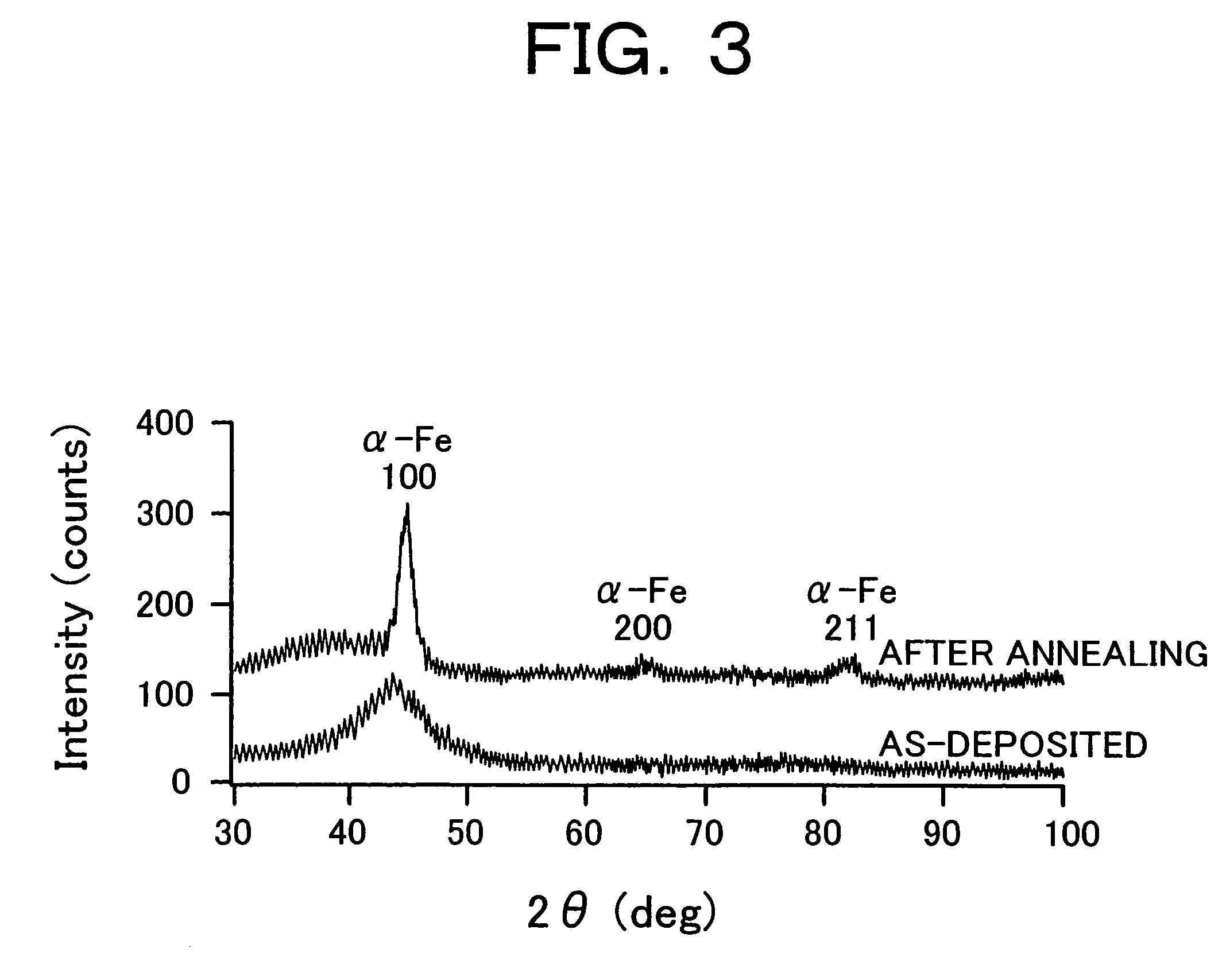
[0049]Samples, in each of which only the soft magnetic underlayer was formed on the glass substrate, were used to examine the crystallinity by the thin-film X-ray diffraction (a Cu-K α ray was used, an X-ray incident angle θ: 2 degrees). All the samples showed only broad peaks peculiar to the amorphous material before annealing. However, afte...


PUM

PropertyMeasurementUnit
thicknessaaaaaaaaaa
thicknessaaaaaaaaaa
thicknessaaaaaaaaaa

Abstract

A double layer perpendicular magnetic recording medium having a high medium S / N ratio at a recording density of 50 Gb / in2 or higher and a magnetic storage apparatus with a lower error rate and excellent reliability are provided. In a perpendicular magnetic recording medium in which a soft magnetic underlayer 12, an intermediate layer 13, and a perpendicular magnetic recording layer 14 are sequentially formed on a substrate 11, the intermediate layer 13 is made to be a non-magnetic amorphous alloy, in which Ni is a main component and Zr is contained, and the soft magnetic underlayer 12 is constituted of ferromagnetic nan-crystals precipitated by annealing.

Description

[0001]This is a continuation of application Ser. No. 09 / 785,416 filed 20 Feb. 2001 now U.S. Pat. No. 6,759,148 claiming priority to JP 2000-266093 filed 1 Sep. 2000, the contents of which are incorporated herein by reference in their entirety.BACKGROUND OF THE INVENTION[0002]1. Field of the Invention[0003]The present invention relates to a magnetic storage apparatus and a magnetic storage medium, particularly to a magnetic storage apparatus having a recording density of 50 Gb / in2 or higher and a magnetic storage medium to achieve the recording density.[0004]2. Description of the Related Prior Art[0005]In recent years, an amount of information handled by computers has been steadily increased, and a larger capacity and higher transfer rate are more and more required of a magnetic disk storage device of an external storage device. So far, a magnetic disk storage device having the maximum recording density of 10 Gb / in2 class has been commercialized. This kind of magnetic disk storage de...

Claims


Application Information

Patent Timeline
Patent Type & Authority Patents(United States)
IPC IPC(8): G11B5/667G11B5/738G11B5/00G11B5/64G11B5/66G11B5/73
CPCB82Y10/00B82Y25/00G11B5/00G11B5/3909G11B5/653G11B5/667G11B5/7325G11B2005/0029G11B5/7368G11B5/66G11B5/1278Y10S428/90
Inventor TANAHASHI, KIWAMUKIKUGAWA, ATSUSHIHONDA, YUKIOFUTAMOTO, MASAAKIISHIKAWA, AKIRA
Owner HITACHI LTD
Learn More