Multi-layer nanoshells comprising a metallic or conducting shell

Inactive Publication Date: 2006-12-05
RICE UNIV
9 Cites 123 Cited by

AI-Extracted Technical Summary

Problems solved by technology

A disadvantage of this approach was its reliance on bulk dielectric properties of the materials.
Despite the theoretical speculation, early efforts to confirm tunability of the plasmon resonance were unsuccessful due to the inability to make a particle having a metal shell on a dielectric core with sufficient precision so as to have well-defined geometrical properties.
Thus, attempts to produce particles having a plasmon resonance in keeping with theoretical predictions tended to result instead in solutio...

Method used

[0084]The metal shell can be any metal that has been previously disclosed as being used in the synthesis of metal nanoshells. The growth of the metal shell can be facilitated by any of the previously disclosed methods.
[0085]In one embodiment, growing a second shell includes attaching APTES to the coating, attaching gold colloids to the APTES, and reducing additional gold onto the gold colloid. The present inventors discovered that improved results for subsequent seeding with gold colloid, and growth of the second shell were obtained by bringing a solution of a coated particle and APTES to a rolling boil in ethanol, preferably at a temperature of about 70° C.
[0091]Metal clusters were attached to the linker molecules on the core by immersing the derivatized core particles in a metal colloid bath. Any metal that can be made in colloidal form could be attached as a metal cluster. For example, silver, platinum, palladium, lead and the like could be used. In addition, metal-like organic molecules are suitable. Such compounds include polyacetylene and polyaniline. Gold clusters having a diameter of 1–3 nanometers were grown using the reduction reaction as described by D. G. Duff, et al., Langmuir 9, pp. 2310–2317 (1993), which is incorporated herein by reference to the extent such methods are disclosed. A solution of 45 ml of water, 300 microliters of 1 M NaOH and 1 milliliter of a freshly diluted 1% aqueous solution of tetrakis(hydroxymethyl)phosphonium chloride (THPC) was stirred in a 100 milliliter flat bottom beaker with a pyrex coated magnetic stir bar. After 2 minutes, 2 ml of chloroauric acid (25 mM dark-aged stock solution, hydrogen tetrachloroaurate (III) trihydrate 99.999% from Aldrich) was added. This reaction mix was used to form gold particles in solution with an average particle diameter of 1–2 nanometers. To increase the size of the particles, higher concentrations of gold chloride could be used. Particles prepared in this fashion were referred to as ultra small gold particles or (UG).
[0097]The dialysis included containing the dilute solution in a 6 kD–8 kD molecular weight cut-off (MWCO) dialysis tubing in the form of a Spectra/PorTR regenerated cellulose membrane, available from SpectrumTR Laboratories. This tubing contains about 6.5 mL of solution to about 1 cm of tubing. A magnetic suspended bag set-up was used in conjunction with the tubing. This set-up has the advantage that it agitates the subparticle solution enough to keep the subparticles better suspended during the process. Without sufficient agitation, the subparticles tend to fall out very early in the dialysis process and this tends further to result in subsequent poor silica growth. The standard clips, available as Spectra/PorTR Standard Closures from SpectrumTR Laboratories were used to seal the bag leaving a small air pocket at the top of the bag (e.g. about 1 cm). The volume of the reservoir was ×100 the volume of the dilute solution. Alternatively, having a ratio of solution volume to reservoir volume of 40 mL:2000 mL was observed to produce no appreciable drop off in effectiveness.
[0102]Coating the subparticles included mixing a solution containing functionalized subparticles with a solution of sodium silicate. A solution of functionlized subparticles was transferred to a beaker and stirring begun with a stir-bar. The appropriate amount of a 0.54% wt silicate solution was added, as determined from spreadsheet as described above. The resulting solution was stirred for about 1 mm. The solution was transferred to dialysis tubing and dialysis was carried out for 24 hrs using the magnetic suspended bag set-up with a fresh reservoir of Milli-Q water. It is believed that the dialysis tends to remove excess silicate that is not depositing on the subparticle's surface. This has the advantage of tending to prevent excess silicate from forming residual silica particles in solution and reduce silica particles growing together. After 24 hrs. the solution of coated particles was removed from the dialysis bag. Any flocculated particles were redispersed by gently rolling the bag between a person's fingers. The bag was preferably rinsed with Milli-Q water to make sure all the particles were removed. The particles were washed in a centrifuge at least 2 times. It was observed that a way to tell if the process was successful is du...

Benefits of technology

[0014]According to any one of the above-described embodiments, the nanoparticle preferably has a plasmon resonance associated with the metallic shell. Further, the plasmon resonance preferably has improved thermal stability with respect to a compara...

Abstract

Composite particles containing metallic shell layers are provided. The particles may include a coating layer, such as of a protective or electrically non-conducting material, over an outermost metallic shell layer. The particle preferably has a plasmon resonance associated with at least one metallic shell layer. The coating layer preferably imparts improved thermal stability to the plasmon resonance. Further, the present invention relates to particles that include at least two metallic shell layers, separated by a coating layer. The addition of a second metallic shell layer preferably allows the plasmon resonance of the shell layer to be more red-shifted with respect to a colloidal particle of the metal that the plasmon resonance of a particle of the same size but with only a single metallic shell.

Application Domain

Technology Topic

Image

  • Multi-layer nanoshells comprising a metallic or conducting shell
  • Multi-layer nanoshells comprising a metallic or conducting shell
  • Multi-layer nanoshells comprising a metallic or conducting shell

Examples

  • Experimental program(5)

Example

Example 1
Providing a Subparticle Having a Silica Core and a Gold Shell
[0087]Silica particles were grown using the Stöber method, described in W. Stöber, et al. Journal of Colloid and Interface Science 26, pp. 62–69 (1968), which is incorporated herein by reference. The silica particles produced each had a spherical shape, were approximately uniform in size, and had a standard deviation of less than 10% (4% is routinely achievable). Tetraethyl orthosilicate (TEOS) 99.999% was obtained from Aldrich Chemical Co., sodium hydroxide was from Fluka Chemical Co. and highly purified water was obtained from a Millipore “TOTALQ” system that included “MILLIQUV” and “MILLIQRO” filters. All glassware was cleaned with chromic acid solution and thoroughly rinsed with “TOTALQ” water.
[0088]Variations in base concentration, and TEOS concentration were used to produce monodisperse silica spheres of various sizes. Temperature and electrolyte concentration also affected the final diameter of the particles. Generally, the following concentration ranges were used: 0.1 to 0.5 M TEOS, 0.5 to 17 M H2O, and 0.5 to 3.0 M ammonia. In addition, a variety of alcohols were used as solvents, however, ethanol was preferred. Higher ammonia concentrations provide larger particles.
[0089]Uniform particles having a diameter of 120 nanometers as measured by a transmission electron microscope (TEM) were prepared by the following method. Approximately 50 milliliters (ml) of dry (100%) ethanol and 4 ml of NH4OH (25% NH3 in water), were stirred in a glass beaker. To this solution, 2.2 ml of tetraethyl orthosilicate having a purity of at least 99.999% was added and allowed to stir for at least 8 hours. By varying the concentrations of NH4OH, water and silicate among other factors, the size of the silica particle was varied from approximately 20 nanometers to 500 nanometers diameter. Larger core particles were grown using a seeded growth technique where additional TEOS and water were added to already formed silica particles. Multiple additions of small amounts of additional reactants allowed monodisperse core particles to be grown as large as 4 microns.
[0090]10 milliliters of a silica particle suspension such as prepared as described above, was added to a 50 milliliter glass beaker. Next, pure aminopropyltriethoxy silane (APTES) was added to the solution. Based on estimates, enough silane was added to coat the particles with multiple layers of silane. For example, 40 microliters of undiluted APTES was used for particles having diameters of 120 nanometers. The solution was stirred for 2 hours, diluted to 200 milliliters and then heated to a boil for four hours. The heating step promotes the reaction of silanol groups into Si—O—Si bonds and strengthens the attachment of the silane to the silica. This mixture was centrifuged at 2000× g for 30 minutes. The supernatant was decanted off and the pellet was redispersed ultrasonically. This washing procedure was repeated five times.
[0091]Metal clusters were attached to the linker molecules on the core by immersing the derivatized core particles in a metal colloid bath. Any metal that can be made in colloidal form could be attached as a metal cluster. For example, silver, platinum, palladium, lead and the like could be used. In addition, metal-like organic molecules are suitable. Such compounds include polyacetylene and polyaniline. Gold clusters having a diameter of 1–3 nanometers were grown using the reduction reaction as described by D. G. Duff, et al., Langmuir 9, pp. 2310–2317 (1993), which is incorporated herein by reference to the extent such methods are disclosed. A solution of 45 ml of water, 300 microliters of 1 M NaOH and 1 milliliter of a freshly diluted 1% aqueous solution of tetrakis(hydroxymethyl)phosphonium chloride (THPC) was stirred in a 100 milliliter flat bottom beaker with a pyrex coated magnetic stir bar. After 2 minutes, 2 ml of chloroauric acid (25 mM dark-aged stock solution, hydrogen tetrachloroaurate (III) trihydrate 99.999% from Aldrich) was added. This reaction mix was used to form gold particles in solution with an average particle diameter of 1–2 nanometers. To increase the size of the particles, higher concentrations of gold chloride could be used. Particles prepared in this fashion were referred to as ultra small gold particles or (UG).
[0092]Generally, the UG solution was mixed with silica particles in an amount that would theoretically cover the core particle surface five to ten times. The solution was allowed to react for 3 hours under gentle stirring. In the preferred embodiment the gold was used 5–30 days after it was made.
[0093]Typically, after three hours, unreacted gold colloid was separated from the gold-decorated silica particles by centrifugation at 1000 RCF. The minimum amount of centrifugal force required to effect separation was used to avoid coalescence of the particles. Particles were washed twice by resuspension and centrifugation.
[0094]Deposition of gold proceeded using a variety of reducing agents such as hydroxylamine hydrocholoride, sodium borohydride, and formaldehyde. Formaldehyde was preferred. In one example, a solution of 25 mg anhydrous potassium carbonate was added to 100 milliliters of water containing 1.5 milliliters of 25 mM chloroauric acid solution (PCG). This solution was allowed to age in the dark for one day. Approximately 10 milliliters +/−5 milliliters of PCG was rapidly stirred with 2–5 milliliters of the gold clustered silica solution. A 100 microliter aliquot of freshly prepared formaldehyde solution (2% by volume in water) was slowly added.

Example

Example 2
Forming a Silica Coating
[0095]A solution of subparticles each having a silica core and a gold shell was prepared using APTES to functionalize silica cores, attaching gold colloid to the silica cores, and reducing additional gold onto the gold colloids. This method is exemplified in Example 1 above. It has been observed that a silica coating can be grown on a subparticle having a partial shell just as easily as on a subparticle having a complete shell.
[0096]Purifying the subparticle solution included performing dialysis on the solution. Between about 20 and about 40 mL of a dilute aqueous subparticle solution having a concentration between about 108 and about 1010 particles/ml. The ultrapure water was Milli-Q water with no additives. This water was de-ionized and uv-irradiated. This water tended to be slightly acidic, that is with a pH between about 5 and about 7. The concentration of the subparticle solution was not observed to effect the dialysis process for concentrations in the range of 108 to 1010.
[0097]The dialysis included containing the dilute solution in a 6 kD–8 kD molecular weight cut-off (MWCO) dialysis tubing in the form of a Spectra/PorTR regenerated cellulose membrane, available from SpectrumTR Laboratories. This tubing contains about 6.5 mL of solution to about 1 cm of tubing. A magnetic suspended bag set-up was used in conjunction with the tubing. This set-up has the advantage that it agitates the subparticle solution enough to keep the subparticles better suspended during the process. Without sufficient agitation, the subparticles tend to fall out very early in the dialysis process and this tends further to result in subsequent poor silica growth. The standard clips, available as Spectra/PorTR Standard Closures from SpectrumTR Laboratories were used to seal the bag leaving a small air pocket at the top of the bag (e.g. about 1 cm). The volume of the reservoir was ×100 the volume of the dilute solution. Alternatively, having a ratio of solution volume to reservoir volume of 40 mL:2000 mL was observed to produce no appreciable drop off in effectiveness.
[0098]The concentration of the purified solution of suparticle solution was determined by UV/Visible Spectroscopy. This concentration was entered into a customized Excel spreadsheet in order to compute apredetermined amounts of silicate for coating the subparticles and APTES for functionalizing the subparticles. The predetermined amount of APTES was a slight excess over the amount associated with the formation of a monolayer of the functionalizing reactant. The predetermined amount of silicate was at least enough to form a 4 nanometer thick coating of silica. It was observed that if either amount was off by an order of magnitude or more then results of the silica growth process were unpredictable.
[0099]The method used for coating the subparticle with silica was based on the method for coating a solid gold core with silica disclosed in L. M. Liz-Marzan, et al., Langmuir 12, 4329–4335 (1996), hereby incorporated herein by reference.
[0100]Functionalizing the subparticles included mixing a solution of subparticles with a solution of APTES. APTES (at least 100 μL) was used to prepare a 1 mM solution of APTES in Milli-Q water (4.70 μL APTES to 20 mL water). The subparticle solution was removed from the dialysis and any flocculated subparticles were redispersed by gently rolling the bag between a person's fingers. The bag was preferably rinsed with Milli-Q water to make sure all the subparticles are removed. The subparticle solution was returned to a centrifuge tube and probed for ˜30 s. The subparticles were preferably used within 12 hours of completing the dialysis as some permanent flocculation may begin if the subparticles are left to stand too long. The subparticle solution was transferred to clean beaker and stirring begun with a stir-bar. The pH of the subparticle solution was checked. The pH of a subparticle solution tends to be about 5. If the pH was not about 5, the pH was adjusted to about 5. A predetermined amount of 1 mM APTES solution was added, where the amount was as determined from a spreadsheet program, as described above. The solution was stirred for about 1 min and allowed to stand for 15 min. The solution was transferred to a centrifuge tube and washed at least once using the same centrifuge speed as used for the unfunctionalized subparticles. The subparticles were redispersed in Milli-Q water and probed for ˜30 s.
[0101]A silicate solution was prepared in advance. In particular, a 0.54% wt solution of sodium silicate (Na2SiO2) at pH=9–11 was prepared. An aliquot of about 27% wt SiO2 was diluted to a desired volume. A 20 mL volume was found to be adequate for several months of laboratory scale preparations of coated subparticles. The pH was adjusted by adding scoops, with a spatula, of an ion exchange resin (IXR, basic, amberlite, prepared earlier), shaking the solution, and letting the solution stand until the beads settled. A pH meter or paper was used to measure the pH. This process was repeated until the desired pH was reached. If the pH was overshot, a very small amount (e.g.<10 μL) of 1 M HCl was added to bring the pH back down. Once the desired pH range was reached, the beads were allowed to settle out and the solution removed by pipette. The solution was run through a syringe filter to make sure there was no large particulate matter left from the IXR.
[0102]Coating the subparticles included mixing a solution containing functionalized subparticles with a solution of sodium silicate. A solution of functionlized subparticles was transferred to a beaker and stirring begun with a stir-bar. The appropriate amount of a 0.54% wt silicate solution was added, as determined from spreadsheet as described above. The resulting solution was stirred for about 1 mm. The solution was transferred to dialysis tubing and dialysis was carried out for 24 hrs using the magnetic suspended bag set-up with a fresh reservoir of Milli-Q water. It is believed that the dialysis tends to remove excess silicate that is not depositing on the subparticle's surface. This has the advantage of tending to prevent excess silicate from forming residual silica particles in solution and reduce silica particles growing together. After 24 hrs. the solution of coated particles was removed from the dialysis bag. Any flocculated particles were redispersed by gently rolling the bag between a person's fingers. The bag was preferably rinsed with Milli-Q water to make sure all the particles were removed. The particles were washed in a centrifuge at least 2 times. It was observed that a way to tell if the process was successful is during the wash cycle. Particles with a thin silica layer tended not to flocculate from using too high a centrifuge speed. Thus, coated particles redispersed more easily than uncoated particles. The coated particles tended to have a thin silica coating of about 4–8 nanometers.
[0103]The particles were redispersed in ethanol to grow a thicker silica shell. The present inventors have observed that the initial thin silica coating does not have to be complete to get a good, thick silica coating. Further, the present inventors have noticed in TEM images that with partially grown metal shells silica can be seen on the metal islands. During seeded growth using the Stöber process, described in W. Stöber, et al. Journal of Colloid and Interface Science 26, pp. 62–69 (1968), which is incorporated herein by reference, the silica layer gets thicker and does coalesce to form a continuous silica shell. In the Stöber process, an ethanol solvent is used. It has been observed that this solvent tends to produce better results that an ethanol:water mixture in a ratio of 4:1. In a typical recipe, 20–40 mL sample of thin silica-coated particles in EtOH was diluted by 60–120 mL EtOH with 3–5 mL of NH4OH added and 0.5–1.1 mL of TEOS added. It was found that residual silica growth could be eliminated by slow addition of TEOS. Further, it was observed that an optimal growth pushed the limit of TEOS addition, and the resulting solution will have just the slightest hint of cloudiness to it. Such a solution had very small silica particles in it, but these were easily separated out in a thorough centrifuge wash process. The solution was stirred overnight at least 8 hours. The solution containing coated particles was centrifuged and redispersed in ethanol about 4–6 times. This had the advantage of tending to prevent formation of large particulate matter. When this matter was observed, it was almost a gel and the inventors believe that it is residual TEOS, small silica particles, or coated particles forming a gel. When it formed, the gel was separated by loosely packing a pasteur pipette with glass wool and filtering the particle solution through.
[0104]The above-described procedure was used to grow silica coatings having a thickness between about 10 nanometers and about 200 nanometers.

Example

Example 3
Enhanced Thermal Stability of Silica-Encapsulated Metal Nanoshells
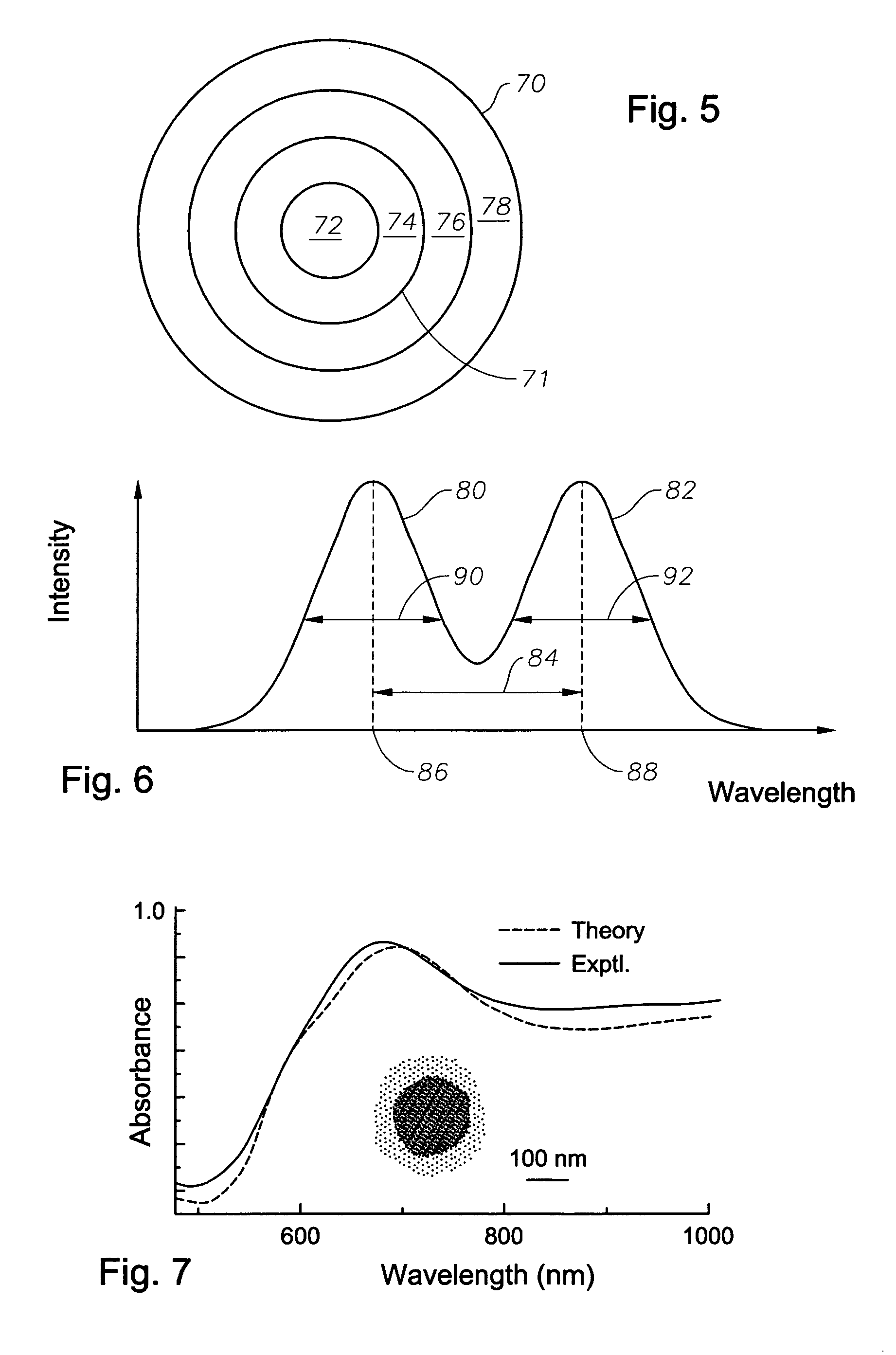
[0105]In this example, fabrication of silica layers onto completed gold nanoshells is described. A series of experiments on silica-encapsulated and uncoated gold nanoshells were conducted, where both their structural and optical properties were observed following heating cycles over a range of temperatures. It was observed that thick (50–70 nm) silica encapsulation layers greatly improved the thermal stability of gold nanoshells, preserving both the structural integrity of the metallic layer and the optical properties of the original nanostructure. For the silica-encapsulated nanoshells, an increase in thermal stability of more than 300 degrees Celsius, relative to uncoated nanoshells, was observed. The effectiveness of this thermally-stabilizing silica layer was observed to be dependent on its thickness: fissures that seemed to appear frequently in thinner layers appeared to compromise the encapsulation, and thus the thermal stabilizing effect of the layer.
[0106]Gold nanoshells were fabricated using a multi-step process that allowed for independent control over the core size and shell thickness. Silica nanoparticles were made using the Stöber method, as described in W. Stöber, et al. Journal of Colloid Interface Science 26, pp. 62–69 (1968), hereby incorporated herein by reference. These particles were then functionalized with 3-aminopropyltriethoxysilane (APTES). Small gold colloid was attached to the functionalized silica particles and gold was reduced onto these seeded particles, which caused the small gold colloid to grow larger and coalesce into a shell. The gold nanoshells were modified by the growth of a silica layer on the surface of the particle, using a procedure developed initially for the encapsulation of small gold colloid. This procedure is described T. Ung, et al., Langmuir 14, 3740–3748 (1998), hereby incorporated herein by reference.
[0107]A surprising result of the present inventors was the discovery that use a solution of nanoshells as typically prepared for spectroscopic analysis resulted in poor formation of a silica coating when using the procedure as described by T. Ung. The inventors discovered that improved results were obtained by passing the nanoshell solution first through dialysis. It is believed that this eliminated impurities remaining from the nanoshell synthesis after standard separation cycles of centrifugation and resuspension.
[0108]FIG. 7 shows a typical absorbance spectrum for an aqueous solution of gold nanoshells coated in a thick silica layer. The spectrum is dominated by the peak at 700 nm, which, when compared to Mie scattering theory for the equivalent core-shell geometry, can be attributed to the quadrupole resonance of the metal shell. The absorbance shoulder, which extends from this feature to longer wavelengths in the near infrared, can be attributed to the dipole resonance of the metal shell. The dipole resonance for these core and shell dimensions occurs at 1105 nm (beyond the spectral range of the spectrometer used). The inset in FIG. 7 is a transmission electron microscope image of an approximately 200 nm diameter gold nanoshell particle with an approximately 60 nm thick silica layer. Particles of this size were used in obtaining the spectrum shown in FIG. 10. In particular, the nanoparticles had an average silica core diameter of 140 nm and an average shell thickness of 30 nm.
[0109]It was experimentally determined that uncoated gold nanoshells began to melt when subjected to a 2–3 hour heating cycle at 275° C. and were completely destroyed following exposure to a 2–3 hr heating cycle of 325° C. By heating cycle is meant that the temperature was raised to the temperature indicated, e.g. 275° C., and held for the indicated amount of time, e.g. 2–3 hr, and allowed to return to room temperature. The temperatures of 275° C. and 325° C. are both significantly below the bulk gold melting temperature of 1064° C. The gold shell was observed to melt at even lower temperatures when cycled for a longer time period, for example when heated at 175° C. for 12 hours. FIGS. 8(a) and 8(b) show results or testing of uncoated and coated nanoparticles having a core diameter of 140 nm and a shell thickness of 30 nm. FIG. 8(a) displays a set of nanoshell extinction spectra where the changes in absorbance following these heating cycles are shown. FIG. 8(a.i) shows spectra of gold nanoshells coated with a 6–8 nm layer of silica. This layer is referred to herein as a thin coating. Following a 3 hour heating cycle at 275° C., the broad maximum of the nanoshell spectrum originally observed at ˜720 nm had shifted to 655 nm and was significantly narrower, suggesting that the shell nanostructure had experienced some changes in morphology. A further heating cycle to 325° C. revealed a further shift in the spectral peak of the optical response. In contrast, nanoshells encapsulated in a 60–70 nm silica layer, referred to herein as a thick coating, experienced only minor modifications in their optical response following heating cycles at 275° C. and 325° C. There is an overall spectral shift of only 20 nm during the initial heating cycle, as seen in FIG. 8(a.ii). This suggests that only minor changes in the nanoshell morphology may have occurred while cycling to this temperature. Further, the spectral shift observed in the initial heating cycle at 275° C. may be due to changes in the index of refraction of the thick silica encapsulant upon heating, such as H2O elimination and further condensation of —OH dangling bonds within the silica network. Virtually no changes in this spectrum were observable between the first and second heating cycle of the sample. In FIG. 8(b) the wavelength of the absorbance peaks shown in FIG. 8(a) is plotted against temperature for each of bare, thin-coated and thick-coated nanoshells. It can be seen in FIG. 8(b) that the absorbance peak for bare gold nanoshells shifts approximately 100 nm when heating from room temperature to 275° C. and shifts a further 50 nm when heated to 325° C. This change in the peak absorbance wavelength can be attributed to melting and destruction of the gold shell.
[0110]FIG. 9(a), 9(b), and 9(c) reveals a set of scanning electron microscope (SEM) images that show the specific structural changes in nanoshell morphology for all samples, following the second heating cycle to 325° C. In FIG. 9(a), the uncoated nanoshells are shown: it is clearly evident that the shell layers were destroyed following the heating cycle to 325° C. The result of melting the gold shell was the formation of large, round gold nanoparticles that no longer coat, but remain attached to, the core silica nanoparticles. This agrees with the observed changes in the extinction spectrum following both heating cycles: the final peak position for the uncoated gold nanoshells occurred at approximately 570 nm, which is typical for large gold colloid.
[0111]This behavior is consistent with the morphology of the gold shell layer in the nanoparticles used for this example. The gold shell layer was formed by electroless deposition onto a colloid-coated silica nanoparticle surface. The initially formed nanoshell layer was thus composed of multiple domains. Such shell layers may even exhibit fissures and cracks that are visible in TEM images of the completed shells. Since melting is initiated at defects and grain boundaries, it is believed that multiple melting initiation sites occur, resulting in coverage of several large spherical gold clusters on the silica nanoparticle surface once the thermal cycling was complete. FIG. 9(b) shows gold nanoshells encapsulated within a thin (6–8 nm) silica layer. These particles began to melt at the visible fissures, but remained predominantly intact after being exposed to heat at 325° C. This result suggests that the thin silica coating existed primarily on the gold and did not necessarily span, that is, extend over, the fissures. The partially increased resilience of the gold shell at elevated temperatures may then be attributed to the presence of the thin silica layer, which partially stabilized the gold layer, preventing it from melting completely and forming gold nanospheres. Finally, in FIG. 9(c) SEM images of gold nanoshells encapsulated with a (50 nm) thick silica layer are shown, following successive heating cycles at 275° C. and at 325° C. The morphology of the gold shell is visible in the SEM image through the thick silica layer, and it appears to be unaltered following both heating cycles, indicating that there was very minimal, if any, melting of the gold shell within the silica encapsulant. Thus, the inventors believe that the silica encapsulant stabilized the gold shell over the range of temperatures where an uncoated shell would begin to melt by binding to the external surfaces and features where melting could be initiated. Also, the interior silica-gold interface did not appear to have as dominant a role in initiating melting as the existence of the external surface. The surface free energy of the gold shell was decreased by the existence of the silica shell, therefore raising the melting point of the nanoscale gold shell structure. Further, in further studies these encapsulated nanoparticles remained unaltered under heating cycles up to 600° C.
[0112]In summary, a sufficiently thick (60–70 nm) silica encapsulation layer grown around a composite nanoparticle has the advantage of greatly enhancing the thermal stability of coated nanoparticles relative to corresponding uncoated nanoparticles. For the case of gold nanoshells, an increase in destructive melting temperatures of approximately 300 degrees relative to uncoated nanoshells was observed. This thermal stabilizing encapsulant layer greatly improves the robustness of Metal Nanoshells for optics and photonics applications, particularly in the context of high-power laser excitation, and may prove useful in preparing metal nanoshells for incorporation in other nanoscale photonic materials and nanostructures.

PUM

PropertyMeasurementUnit
Temperature300.0°C
Temperature600.0°C
Length7.0E-7m
tensileMPa
Particle sizePa
strength10

Description & Claims & Application Information

We can also present the details of the Description, Claims and Application information to help users get a comprehensive understanding of the technical details of the patent, such as background art, summary of invention, brief description of drawings, description of embodiments, and other original content. On the other hand, users can also determine the specific scope of protection of the technology through the list of claims; as well as understand the changes in the life cycle of the technology with the presentation of the patent timeline. Login to view more.

Similar technology patents

Acetylacetone based composite heat stabilizer

InactiveCN101508636AImprove thermal stabilityPreparation of aldehyde/ketone chelatesAcetylacetoneMagnesium
Owner:BEIJING UNIV OF CHEM TECH

Classification and recommendation of technical efficacy words

Why Eureka
Try Eureka