Coated carbide tap

a technology of coated carbide and tap, which is applied in the field of cutting tools, can solve the problems of reducing the useful cutting speed, reducing the fracture toughness and strength of cemented tungsten carbide, and moderate resistance to temperatur

Inactive Publication Date: 2006-12-12
KENNAMETAL INC +1
View PDF38 Cites 28 Cited by
  • Summary
  • Abstract
  • Description
  • Claims
  • Application Information

AI Technical Summary

Problems solved by technology

It is well known that cutting tools generate temperatures that are high enough to limit the life of the tool, thereby reducing the useful cutting speed.
Although high-speed steels have excellent strength and toughness, they have only moderate resistance to temperature compared to materials that are more refractory.
However, cemented tungsten carbide has lower fracture toughness and strength than high-speed steel and this limits its use in some machining operations.
However, forming taps require much higher power than cutting taps and produce an imperfect thread crest at the thread's minor diameter.
Unlike most other cutting tools used, for example, in turning, milling, drilling and reaming, tapping tools have relatively weak cross sections and additionally the cutting edges are weak.
For this reason, taps manufactured from cemented carbide according to current technology have only very limited use.
When carbide taps of current designs are used, cutting edges chip or fracture easily, rendering the tool useless, even in relatively easy to machine materials, such as steel.
For this reason, carbide taps of the current technology are limited to tapping materials that are even easier to cut than steel, such as aluminum and cast iron.
However, such carbide grades do not have sufficient strength and toughness to be used as a material for taps.
Alternatively, grades containing principally tungsten carbide cemented with cobalt in concentrations over 10% by weight have high strength, but their wear resistance is low in steel machining, and therefore they are not suitable as a tool material for tapping steel.

Method used


Image

  • Coated carbide tap
  • Coated carbide tap
  • Coated carbide tap

Examples


Embodiment Construction

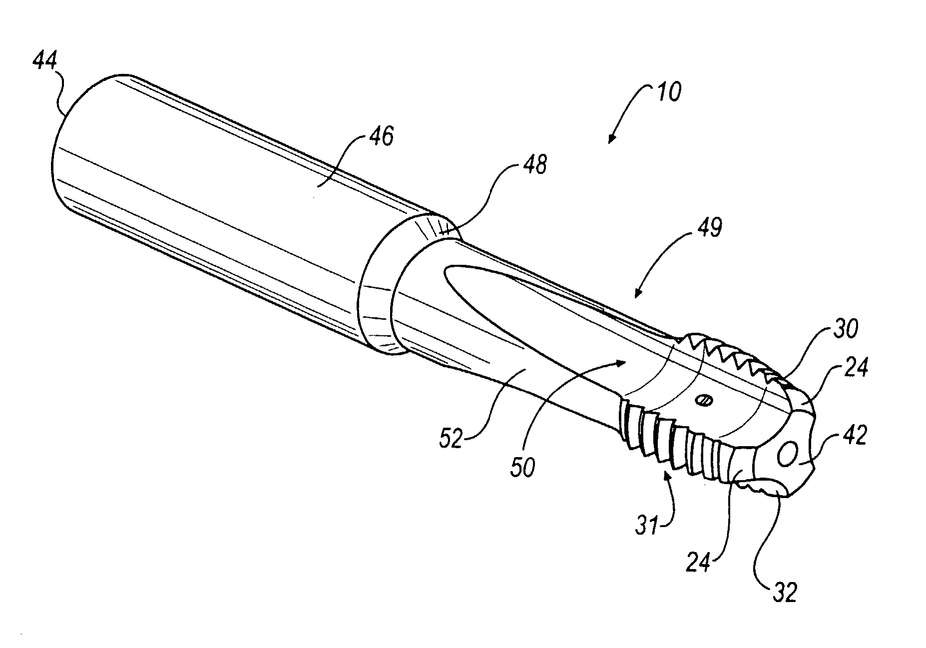
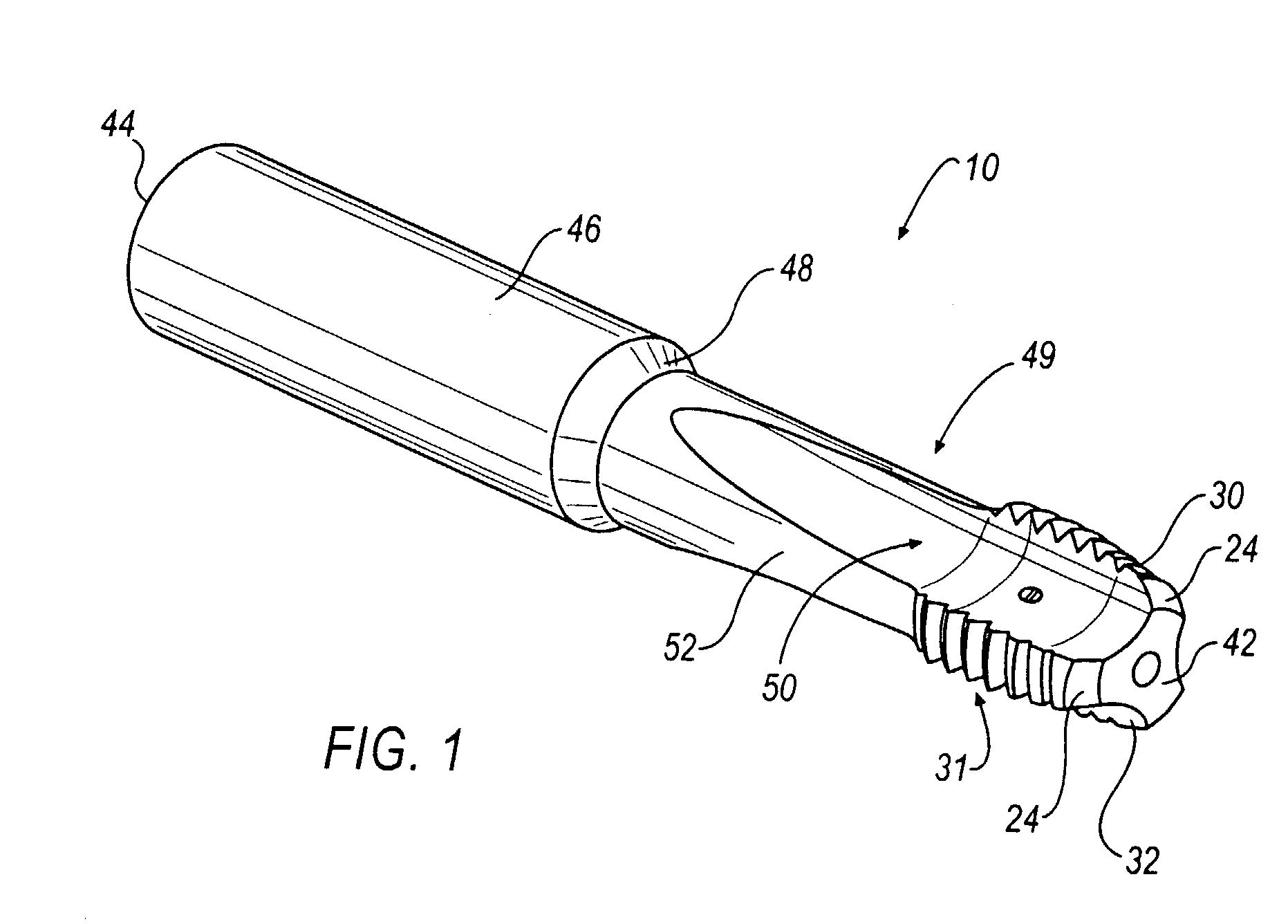
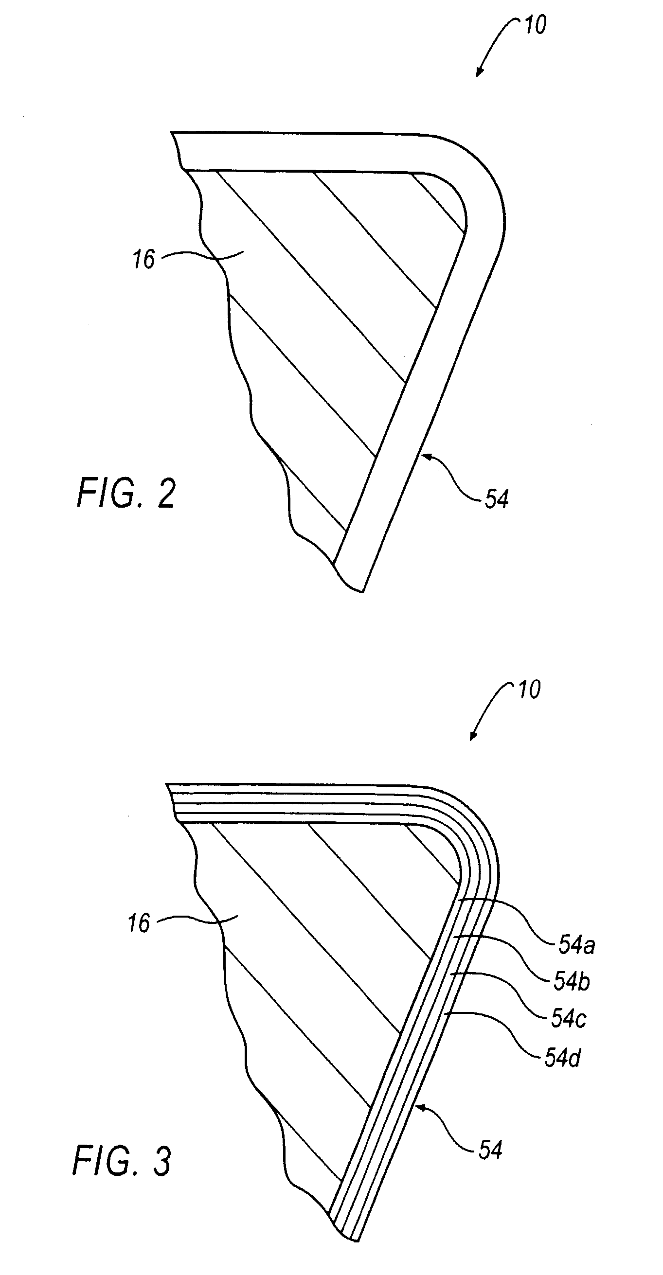
[0020]Referring now to FIG. 1, a precision carbide cemented threading tap, shown generally at 10, is illustrated according to an embodiment of the invention. The tap 10 is manufactured from a cylindrical sintered tungsten carbide blank frequently referred to as a substrate 16 (FIGS. 2–8). The blank has a diameter that is sized larger than the finished dimensions of the tap 10 and is cut to length on surfaces 42 and 44.

[0021]A typical material for the substrate 16 is tungsten carbide cemented with cobalt. The amount of cobalt can range between about 12 weight percent to about 16 weight percent. In addition, small amount of transition metal carbides may be added to restrain grain growth, and the substrate 16 may also contain low levels of impurities that might be picked up during processing.

[0022]The first step in processing the substrate 16 is to grind the blank to precision cylindrical tolerances by methods such as cylindrical traverse grinding on centers or by centerless infeed gri...


PUM

PropertyMeasurementUnit
weight percentaaaaaaaaaa
angleaaaaaaaaaa
wear resistantaaaaaaaaaa

Abstract

A coated carbide tap comprises a substrate consisting of tungsten carbide cemented with 12 to 16% by weight cobalt with additions of small amounts of transition metal carbides added to restrain grain growth, and may also contain low levels of impurities that might be picked up during processing. The substrate is coated with a layer of metal nitrides, carbides, carbonitrides, borides and / or oxides, the metal being chosen from one or more of the following: aluminum, silicon and the transition metals from Groups IVa, Va, and VIa of the Periodic Chart. The coating may comprise a monolayer and / or alternating layers optionally with varying chemical composition. To reduce friction, a top outer layer comprised of molybdenum disulphide; molybdenum disulphide and transition metals, or any combination thereof; carbon; carbon and transition metal carbides, or any combination thereof; carbon and a transition metal, or any combination thereof; and / or carbon nitride may be either co-deposited as a single layer or deposited in multiple or alternating layers to the coating. The coated carbide tap of the invention can be used at cutting speeds at least three times faster than conventional taps without chipping or breaking the tap.

Description

CROSS-NOTING TO RELATED APPLICATION[0001]This application is related to U.S. patent application Ser. No. 10 / 267,387, filed on Oct. 9, 2002, entitled “TOOL WITH WEAR RESISTANT LOW FRICTION COATING AND METHOD OF MAKING THE SAME,” the entire contents of which are incorporated herein by reference.BACKGROUND OF THE INVENTION[0002]1. Field of the Invention[0003]This invention relates to cutting tools. More particularly, this invention relates to a coated carbide tap for threading steels and other ferrous based alloys.[0004]2. Description of the Related Art[0005]It is well known that cutting tools generate temperatures that are high enough to limit the life of the tool, thereby reducing the useful cutting speed. There exists a variety of materials used to manufacture cutting tools. Cutting tools are often manufactured from a class of tool steels known as high-speed steels. Although high-speed steels have excellent strength and toughness, they have only moderate resistance to temperature co...

Claims


Application Information

Patent Timeline
Patent Type & Authority Patents(United States)
IPC IPC(8): B23G1/00B22F9/00B23B51/00B23D77/00B23G5/06B23P15/52B27G15/00B32B9/00B32B9/04B32B15/04B32B18/00B32B19/00C22C5/00C22C29/00C23C30/00
CPCB23G5/06B23P15/52C23C30/005B23G2200/26B23G2225/36B23G2225/48Y10T428/30B23G2225/60B23G2225/56
Inventor HENDERER, WILLARD E.SANTHANAM, ANAKKAVUR T.AKAKI, SADAYUKI
Owner KENNAMETAL INC
Why Eureka
Try Eureka