Sputtering apparatus and film forming method

a technology of sputtering apparatus and film forming method, which is applied in the direction of vacuum evaporation coating, electrolysis components, coatings, etc., can solve the problems of deteriorating magnetic characteristics, inability to obtain desired magnetic characteristics, and limitation of longitudinal magnetic recording density

Inactive Publication Date: 2007-01-02
ANELVA CORP
View PDF26 Cites 16 Cited by
  • Summary
  • Abstract
  • Description
  • Claims
  • Application Information

AI Technical Summary

Benefits of technology

[0016]Under such circumstances, an object of this invention is to provide a sputtering apparatus and a thin film formation method which make it possible to form respective layers of a multilayer film having a clean interface at a optimum temperature, or which make it possible to continuously carry out the film formation and the surface processing. Another object of this invention is to provide a small sputtering apparatus for forming a multilayer film as compared with prior art apparatus.

Problems solved by technology

However, since the crystal grain of a magnetic layer becomes smaller as the film is made thinner, thermal stability falls due to thermal fluctuation or thermal magnetization relaxation phenomenon which causes the super-paramagnetism transition in which the magnetization of micro magnets cannot be maintained at a room temperature.
This is thought to be the limitation of the recording density of longitudinal magnetic recording media.
However, the method for forming a multilayer film by transporting the substrates to a plurality of chambers to form respective layers is disadvantageous that the residual gas in a vacuum adsorbs on the film surface during the substrate transportation and deteriorates magnetic characteristics as a result of the impurities mixing and the oxide layer formation at the interface.
In the case of the multilayer film of very thin layers, especially such as a magnetic recording film composed of repetitions of bilayer of Co and Pd in which each layer has a thickness of 1 nm or less, the residual gas influences remarkably the characteristics, which may make it impossible to obtain desired magnetic characteristics.
Furthermore, the disadvantage of the temperature drop during the substrate transportation cannot be avoided, and therefore it is difficult to set the substrate temperature at an optimum value in respective film forming chambers.
However, it was difficult to meet such demands with prior art apparatuses.
As a result, the surface is contaminated with residual gas during transportation.
In addition, a huge floor space is requested for the apparatus since its size is extremely increased.
Although the disadvantages of prior art apparatus and film forming method have been described for the magnetic disks as an example, similar problems are also anticipated to occur for a variety of elements or devices using magnetic thin films such as a magneto-resistive (MR) head for read / write operation, and multilayer devices or elements composed of various materials other than magnetic materials.

Method used


Image

  • Sputtering apparatus and film forming method
  • Sputtering apparatus and film forming method
  • Sputtering apparatus and film forming method

Examples


first embodiment

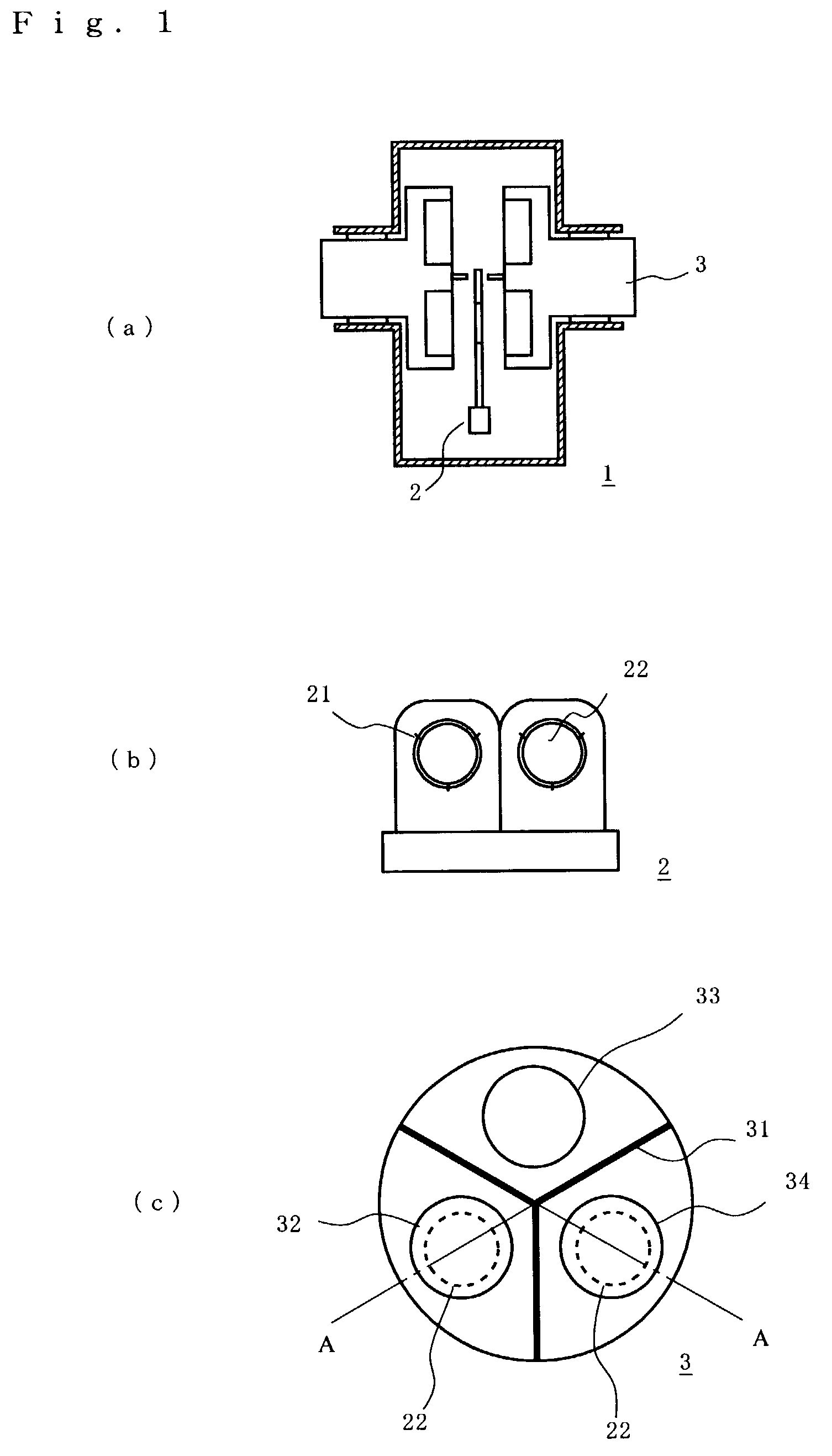
[0036]this invention refers to a sputtering chamber shown in FIGS. 1 and 2 which is used for the formation of a Co / Pd magnetic multilayer film of perpendicular magnetic recording medium shown in FIG. 5 (a). FIG. 1(a) is a schematic cross-sectional view showing a sputtering chamber, seen from the substrate transportation direction. As shown in the drawing, a rotation cathode unit 3 is rotatably installed on each of two sidewalls of the sputtering chamber 1 to cause electric discharge on both sides of a carrier 2 which holding two substrates. Thus, the multilayer film can be simultaneously formed on both sides of substrate.

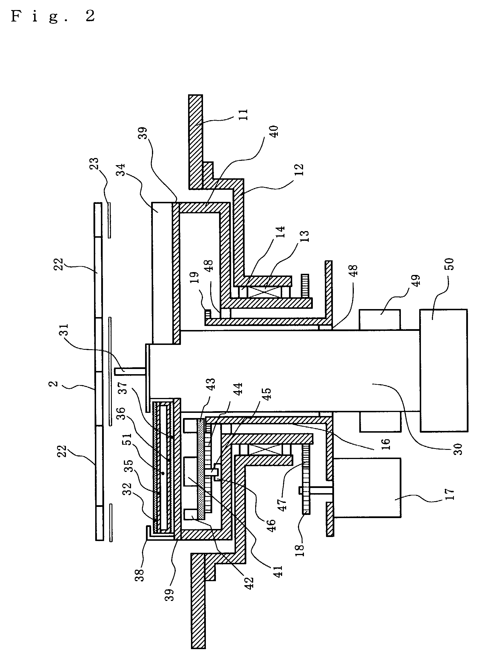
[0037]The substrate 22 is supported with, for example, three support clicks 21 on carrier 2. The carrier is transported to process chambers by the well-known transportation mechanism as is shown in FIG. 1 (b). The transportation mechanism using, for example, a magnetic coupling disclosed in JP10-159934A is preferably employed. This transportation mechanism is compos...

second embodiment

[0051]As this invention, the sputtering chambers are explained, which are used for the formation of underlying and soft magnetic layers (Ti / FeTaC / Ti), and recording layers (Fe / Pt) of magnetic medium shown in FIG. 5(b).

[0052]The underlying and soft-magnetic layer forming chamber and the magnetic recording layer forming chamber are nearly the same as that shown in FIGS. 1 and 2, except for the configuration of target and processing mechanism of the rotation cathode unit. The rotation cathode units of the underlying and soft-magnetic layer forming chamber and the magnetic recording layer forming chamber are shown in FIGS. 3(a) and (b), respectively.

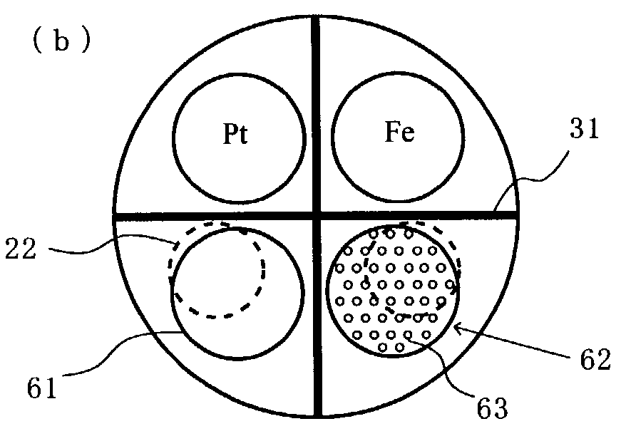
[0053]A Ti target for forming underlying layer, a FeTaC target for forming soft magnetic layer (under layer) to shunt the magnetic field from magnetic recording layers, and heat treatment mechanism 61 are attached on the rotation cathode unit of the underlying and soft-magnetic layer forming chamber.

[0054]An ion irradiation mechanism 62 for ...

third embodiment

[0060]Next, this invention is shown in FIG. 4.

[0061]FIG. 4 is a schematic view showing a sputtering chamber preferably used for forming a TMR (Tunneling magnetoresistive) film of the non-volatile magnetoresistive random access memory (MRAM) using the magneto-resistance effect.

[0062]As shown in FIG. 5(c), a multilayer TMR film is composed of ferri-type pinned layers of CoFe / Ru / CoFe, free layers of NiFe / CoFe, and a barrier (insulator) layer of Al2O3 or the like sandwiched between them. The surface uniformity of lower layer (CoFe) greatly influences the barrier characteristics because the barrier layer is so thin as 1–1.5 nm. That is, the cleanness and uniformity of the lower layer surface is very important.

[0063]In the sputtering chamber shown in FIG. 4(a), the film formation is started when the center of the substrate 22 attached on carrier 2 comes to the position of the rotation cathode unit center. In the case where the film formation is made after the center of substrate 22 is mad...


PUM

PropertyMeasurementUnit
temperatureaaaaaaaaaa

Abstract

The present invention is to provide a sputtering apparatus and a thin film formation method which make it possible to form respective layers of a multilayer film having a clean interface at a optimum temperature, or which make it possible to continuously carry out the film formation and the surface processing. Another object of this invention is to provide a small sputtering apparatus for forming a multilayer film as compared with prior art apparatus. A sputtering apparatus of this invention comprises a main shaft around which at least one target and at least one surface processing mechanism are installed, a substrate holder holding a substrate or a plurality of substrates arranged facing the target and the surface processing mechanism, and a rotation mechanism to rotate the main shaft or the substrate holder.

Description

BACKGROUND OF THE INVENTION[0001]1. Field of the Invention[0002]The present invention relates to a sputtering apparatus and a thin film formation method, and in particular to a sputtering apparatus suitable for producing multilayer thin films having a clean interface.[0003]2. Related Art[0004]The area recording density of a magnetic disk has remarkably increased in recent years, and researches and developments are now made to realize the recording density of 100 Gbit / in2. A magnetic recording medium is classified into a longitudinal (horizontal) magnetic recording and a perpendicular magnetic recording, and the former is now mainly adopted. The recording density of the longitudinal recording medium increases as the product of residual magnetic flux density (Br) and film thickness decreases, and therefore the film thickness has been made very thin in order to increase the recording density. However, since the crystal grain of a magnetic layer becomes smaller as the film is made thin...

Claims


Application Information

Patent Timeline
Patent Type & Authority Patents(United States)
IPC IPC(8): C23C14/35C23C14/34C23C14/22G11B5/851H01L21/687
CPCC23C14/225C23C14/35G11B5/851H01L21/68792H01L21/68771
Inventor OKATANI, KENJIYAMADA, SATOSHIHASEGAWA, YOSHIRO
Owner ANELVA CORP
Why Eureka
Try Eureka