Ultraviolet irradiating device

a technology of ultraviolet light and irradiation device, which is applied in the direction of optical radiation measurement, therapy, instruments, etc., can solve the problem of obstructed resin cure reaction

Inactive Publication Date: 2007-02-06
KEYENCE
View PDF25 Cites 13 Cited by
  • Summary
  • Abstract
  • Description
  • Claims
  • Application Information

AI Technical Summary

Benefits of technology

[0013]A main object of the present invention is to provide an ultraviolet irradiating device for adhesion of part, which is compact and is cheaply manufactured and is excellent in operability by building the light emitting diode in the head portion as a light source.
[0015]Another object of the present invention is to provide an ultraviolet irradiating device able to effectively improve the phenomenon in which no resin is easily cured on its surface while the light emitting diode is used as the light source.
[0020]The ultraviolet irradiating device (claim 1) in the present invention can be made compact and can be cheaply constructed in comparison with the conventional ultraviolet irradiating device in which the head portion and the device main body are connected by an optical fiber cable by using a mercury xenon lamp as a light source. Further, since the head portion and the controller portion are connected by the electric cable, the head portion can be drawn around until a portion separated from the controller section. Further, the intensity of the near-ultraviolet ray irradiated from each head and on-off timing can be individually controlled by an electric signal from the controller section.
[0021]In accordance with a preferable embodiment mode (claim 2), the air near the resin surface is expelled by the inactive gas injected from the head portion, and the density of an oxygen molecule is reduced. Accordingly, the phenomenon of obstructing the curing reaction of the resin by binding the oxygen molecule to a resin molecule is restrained or relaxed. As its result, the effect of approximately uniformly curing the resin surface together with the interior of the resin is obtained. Further, the effect of cooling the generation heat of the light emitting diode by the inactive gas flowed in the housing interior (gas flow passage) of the head portion is also obtained. The light emitting diode emitting the near-ultraviolet ray has large self generation heat in comparison with the light emitting diode emitting normal visible light, and its life is shortened in the case of insufficient heat radiation. However, long life can be secured by the above cooling effect.

Problems solved by technology

Therefore, as mentioned above, the oxygen molecule is bound to the resin molecule near the surface of resin coming in contact with the air, and the curing reaction of the resin is obstructed.

Method used


Image

  • Ultraviolet irradiating device
  • Ultraviolet irradiating device
  • Ultraviolet irradiating device

Examples


embodiment 1

[Embodiment 1]

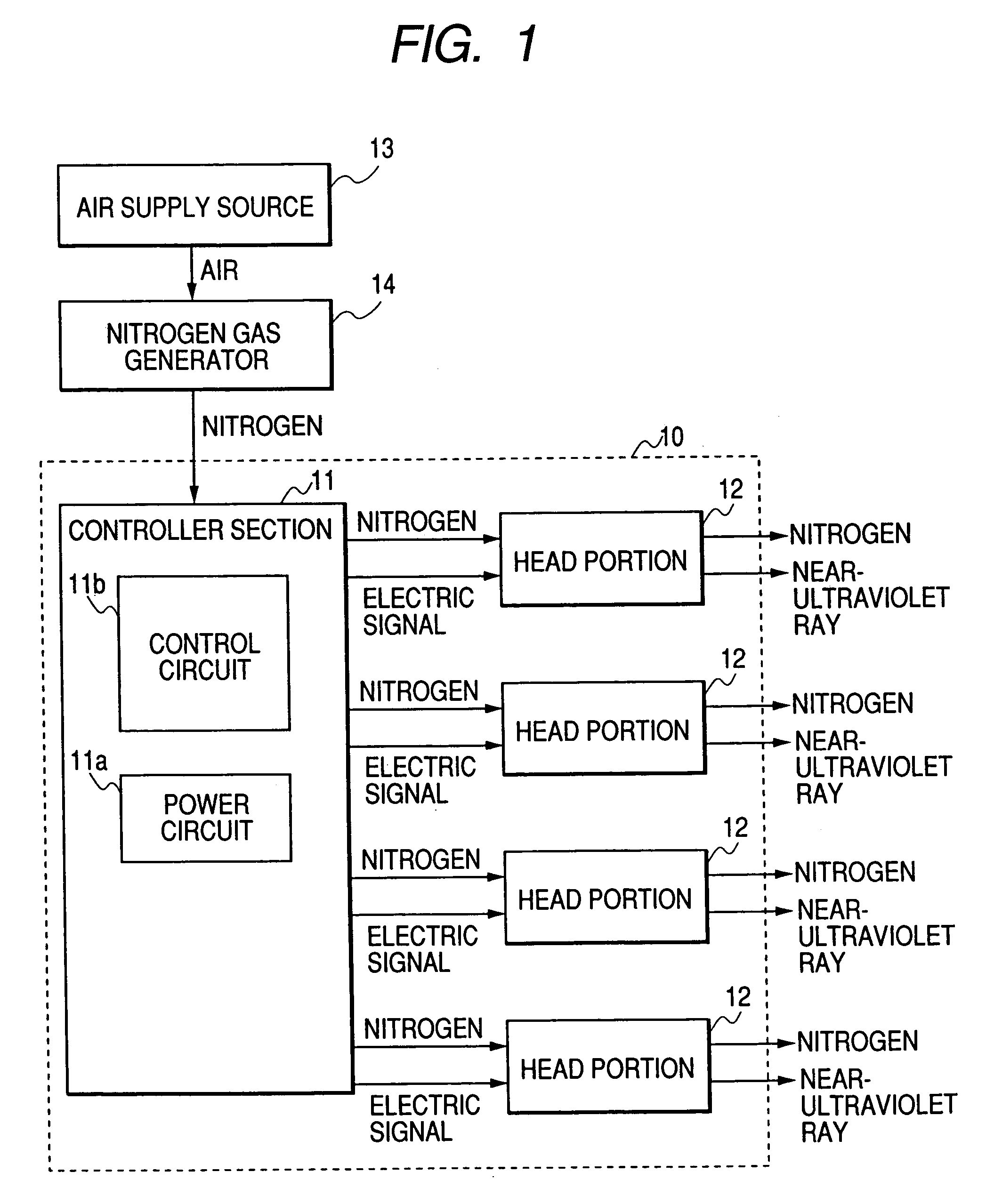
[0040]FIG. 1 is a block diagram showing a constructional example of a resin curing system including an ultraviolet irradiating device in accordance with an embodiment 1 of the present invention. This resin curing system uses an ultraviolet irradiating device 10 constructed by a controller section 11 and plural head portions 12, an air supply source 13 and a nitrogen gas generator 14.

[0041]Air piping can be used as the air supply source 13 in the case of the interior of a factory. A compressor may be directly connected to the nitrogen gas generator 14. The nitrogen gas generator 14 can use a nitrogen gas generator sold at a market and having a system for separating the air into nitrogen and the oxygen enrichment air by a hollow separating film. For example, such a nitrogen gas generator is generally used to prevent oxidation in soldering, heat treatment, etc.

[0042]The nitrogen gas from the nitrogen gas generator 14 is supplied to the controller section 11 of the ultravi...

embodiment 2

[Embodiment 2]

[0076]FIG. 9 is a view showing the external appearance of an ultraviolet irradiating device in accordance with an embodiment 2 of the present invention. In the ultraviolet irradiating device of this embodiment, four head portions 62 at its maximum can be connected to one controller section 61. Four connectors 611 for cable connection are longitudinally arranged in parallel with each other on the left-hand side of the lower portion of a front face panel of the controller section 61, and are sequentially set to channels 1, 2, 3 and 4 from above. In the illustrated example, a head portion 62 is connected to channels 1 and 3 through an electric cable 63. No injecting function of the nitrogen gas is provided in the head portion 62 of the ultraviolet irradiating device of this embodiment. The controller section 61 and the head portion 62 are connected by only the electric cable 63.

[0077]Four indicators 612 and four push button switches 613 are respectively longitudinally arr...

embodiment 3

[Embodiment 3]

[0083]A construction for extending the connecting distance of the controller section and the head portion by using a relay will next be explained as an embodiment 3. As mentioned above, the ultraviolet irradiating device of the present invention has a light source (ultraviolet ray light emitting diode) in each head portion, and the controller section and the head portion are connected by the electric cable. Accordingly, the ultraviolet irradiating device of the present invention can lengthen the connecting distance of the controller section and the head portion in comparison with the conventional ultraviolet irradiating device in which the light source is arranged in the main body portion and the ultraviolet ray is guided until each head portion by using an optical fiber. However, there is a limit in this connecting distance since an electric signal is attenuated. On the other hand, there is a case in which the connecting distance exceeding seven ten meters is required...


PUM

PropertyMeasurementUnit
wavelengthaaaaaaaaaa

Abstract

In an ultraviolet irradiating device in which a controller section and plural head portions used to cure ultraviolet curable resin used in the adhesion of a part are connected by an electric cable, each of the plural head portions has a sleeve-shaped housing and a light emitting diode which is arranged within this housing and emits a near-ultraviolet ray. The ultraviolet irradiating device is constructed such that the near-ultraviolet ray emitted from the light emitting diode is irradiated to the exterior from a near-ultraviolet ray irradiating port arranged on the tip face of the housing. The controller section has a power circuit and a control circuit for individually controlling the operations of the light emitting diodes of the plural head portions.

Description

BACKGROUND OF THE INVENTION[0001]The present invention relates to an ultraviolet irradiating device in which plural head portions which is used to cure ultraviolet curable resin used to adhere a small article part and a controller section are connected by an electric cable.[0002]The ultraviolet curable resin is widely used from the fields of formation and printing of a resist film to the field of adhesive fixation of the small article part in an assembly process of an optical pickup, etc. The ultraviolet curable resin is generally designed so as to be cured by irradiating a near-ultraviolet ray near 365 nm in wavelength. However, a phenomenon (so-called oxygen obstruction) for obstructing a curing reaction of the resin by binding an oxygen molecule to a resin molecule is generated near the surface of the resin coming in contact with the air. Therefore, an ultraviolet ray (of a short wavelength) having large energy for overcoming this generation is required. Namely, it is known that ...

Claims


Application Information

Patent Timeline
Patent Type & Authority Patents(United States)
IPC IPC(8): G01N21/33G21K5/00B05C9/12C08J3/28C09J5/00G01J1/00
CPCG01J1/00B05C9/12
Inventor KATSUKI, KAZUMITSU
Owner KEYENCE
Why Eureka
Try Eureka