Cathodic protection system for metallic structures

a protection system and metallic structure technology, applied in metal-working machine components, metal working apparatus, manufacturing tools, etc., can solve the problems of inability to achieve full cathodic protection, inability to electrically isolate the piping, access problems, etc., to facilitate custom anode designs, improve handling, transport and installation, and facilitate customer us

Inactive Publication Date: 2007-03-06
BENHAM ROGER A
View PDF8 Cites 27 Cited by
  • Summary
  • Abstract
  • Description
  • Claims
  • Application Information

AI Technical Summary

Benefits of technology

[0016]The present invention is directed to an improved cathodic protection system, which may at least partially overcome the abovementioned disadvantages or provide the consumer with a useful or commercial choice.
[0026]In a particularly preferred embodiment, the electrical grounding means and / or the portion of the system between the rectifier element and the consumable anode may have a low resistance.
[0033]According to another aspect, the invention resides in a method of installing and transporting an anode and backfill materials comprising providing a container for holding a predetermined amount of backfill material for a particular anode hole size with the anode attached to the container, digging an anode hole corresponding to the amount of backfill material provided, placing the anode in the hole and placing the backfill material in the hole. This invention includes the formation of a container capable of assisting cleanly and efficiently transporting and installing the anode and backfill material. The preferred embodiment of the invention is a container with a screw-cap on one end. The container holds a quantity of backfill predetermined by the engineer or designer, typically a powdered or granular coke-breeze carbon graphite material, and / or a powdered gypsum bentonite material. This container may be reused over and over again, with a deposit or core charge arrangement with the customer, which would conserve resources and be beneficial to the environment not having to constantly throw away the packaging material.
[0035]Also, because of the varied earth-grounding characteristics, in terms of soil-resistivity and conductivity, many different anode ground bed configurations may be required. There is no one anode size that is ideal and what may work at one location may not work at another. Therefore, the method of installing and transporting the anode material facilitates custom anode designs that are quick and easy to use for the customer.
[0036]The above mentioned container preferably includes a rigid tube with a removable endcap that is made in a′predetermined size to provide the exact amount of backfill that is required for the specified anode and hole size configuration. The rigid tube may incorporate a handle and a strapping mechanism to attach the backfill and the corresponding anode together for improved handling, transport and installation. This configuration may provide for a more effective means for managing the anode and backfill materials on the job site. Also, this packaging method may enable a lessor experienced contractor or do-to-yourself installer, who may not have the ability to determine anode and backfill size and quantity requirements, to install cathodic protection on their own without the assistance of an experienced installer. Also, this packaging method lends itself well to easier shipping and direct mail delivery to the customer.

Problems solved by technology

There are cases where full cathodic protection cannot be achieved without electrically isolating the structure to be protected.
With regard to the application of cathodic protection for buried piping associated with commercial or residential buildings, electrical isolation of the piping is practically impossible, and not legal in many cases.
With typical building construction, the piping is buried below the concrete foundation and flooring slab, and projects upwardly through the concrete slab at numerous service locations within the building inside walls and concealed spaces, creating access problems and numerous potential areas for electrical contact, or “shorting”, to the building grounding system.
Therefore, an attempt to isolate below-slab metallic piping is usually not practical due to the many inaccessible locations that would require dielectric insulators.
Legally, in many if not all cases, it would be against building codes and regulations to electrically isolate piping within a commercial or residential building.
This is due to safety issues related to the electrical grounding requirements, where the piping is grounded to provide a low resistance path to earth for the electric circuit-breakers to work.
The conducting structure could be a living creature such as a human being and completion of the electrical circuit would generally lead to electrocution.
This fixed voltage limits the current output, especially in higher resistance soils, and often makes the active system an expensive and generally poor choice for protection of bare or poorly coated structures that are not able to be electrically isolated.
In the cathodic protection installation and service industry, a cross-connection of the output leads is a very serious and real concern.
This results in the structure being oxidized at an accelerated rate, and the consumable anode(s) being protected; the exact opposite of what is trying to be accomplished with a typically expensive cathodic protection system.
This is especially bad if the structure that is damaged transports or stores flammable gas or petroleum oil.

Method used


Image

  • Cathodic protection system for metallic structures
  • Cathodic protection system for metallic structures
  • Cathodic protection system for metallic structures

Examples


Embodiment Construction

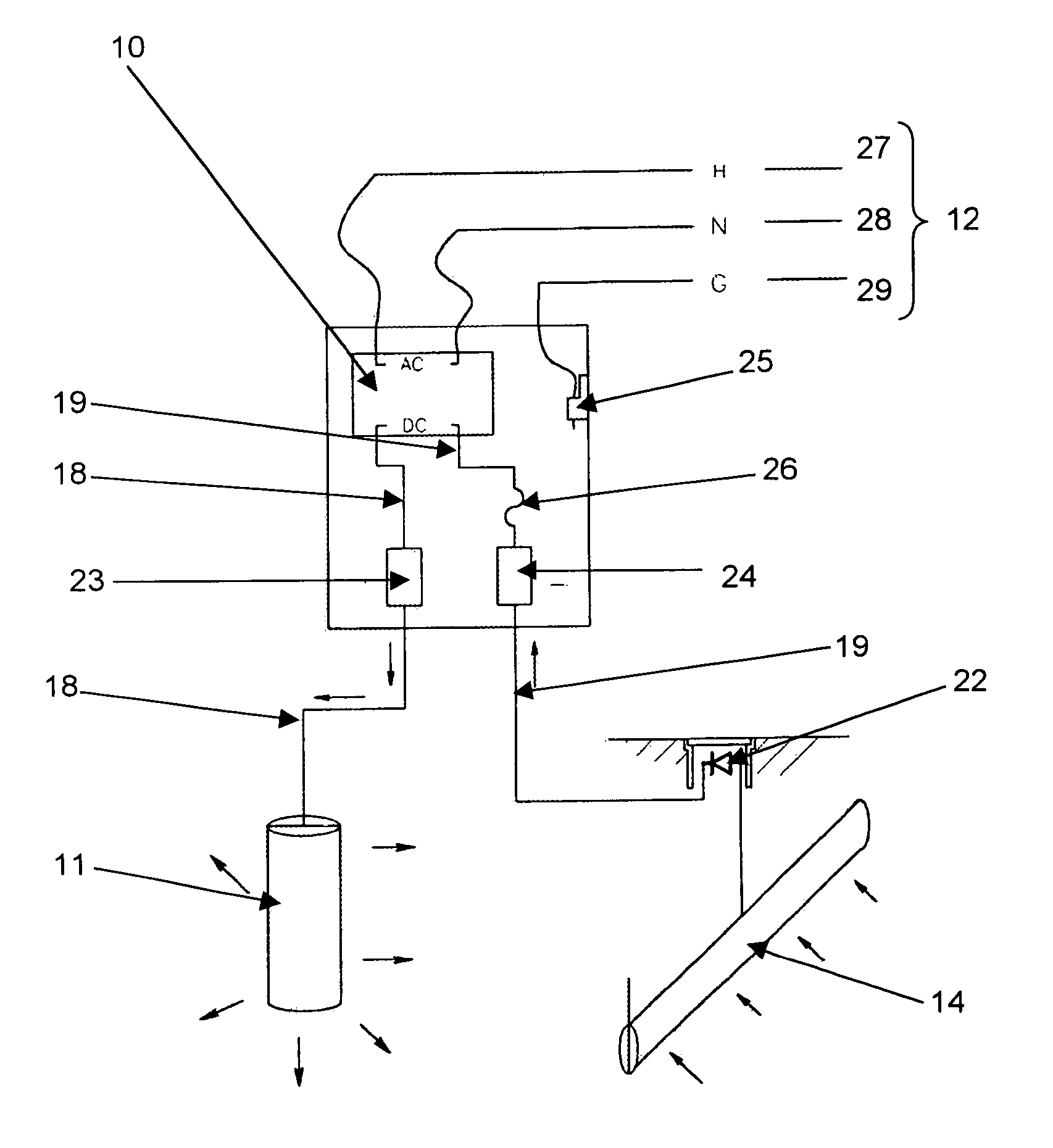
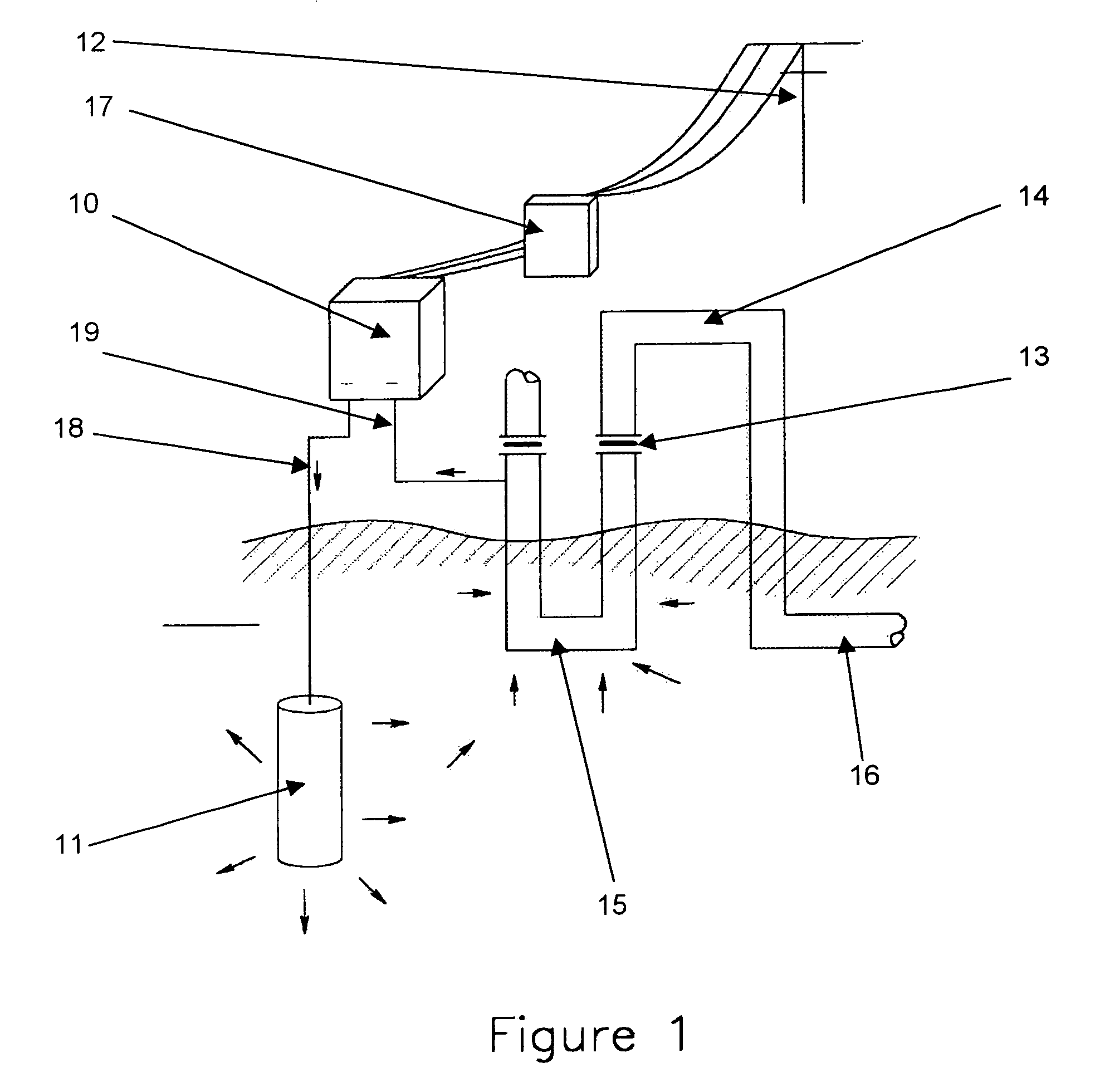
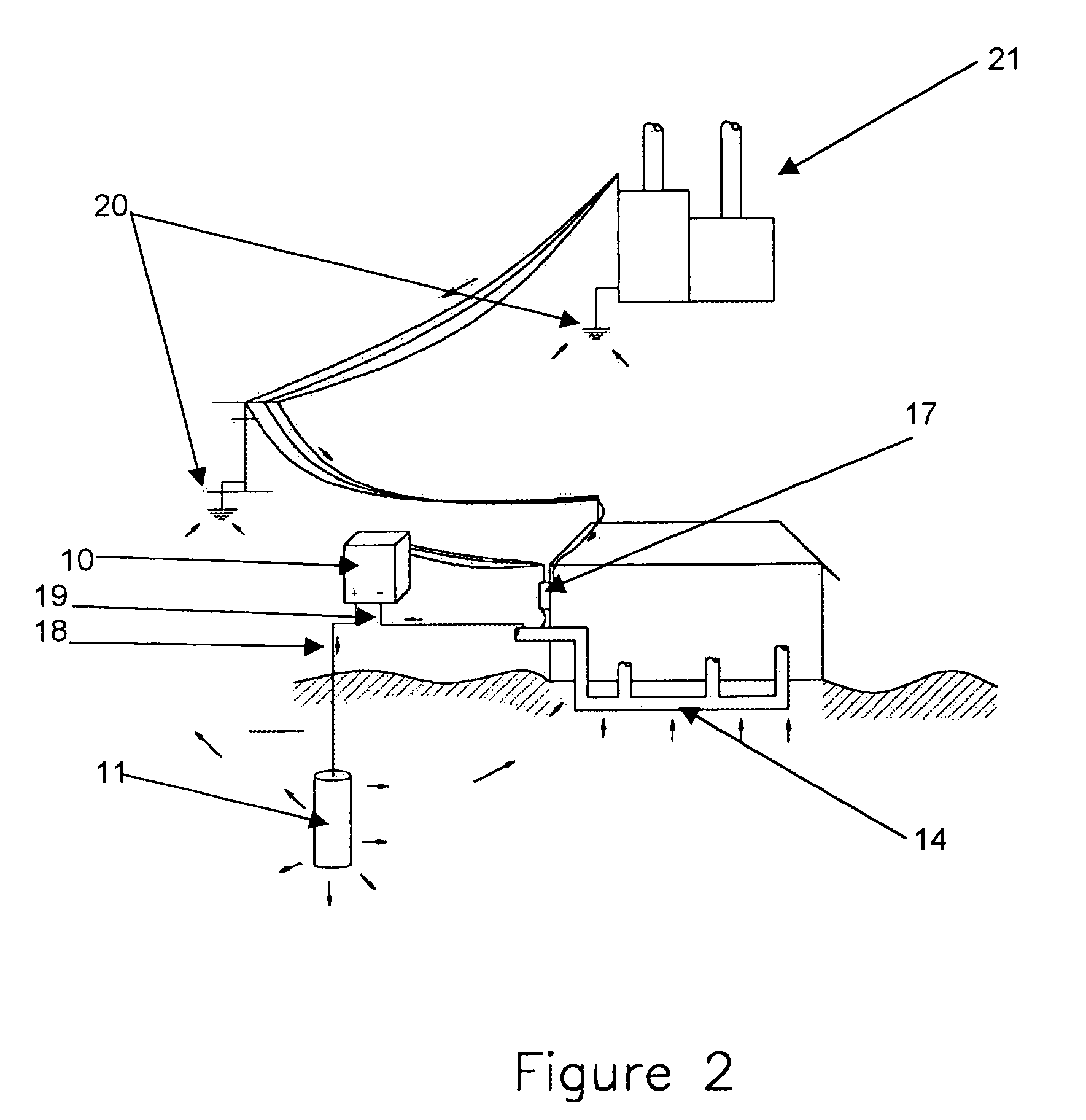
[0045]With reference to FIGS. 1 through 8, the cathodic protection system is there illustrated which exemplifies the present invention. The system as shown comprises a DC power supply rectifier, a consumable anode installed in the earth, associated wiring, and the protected piping.

[0046]FIG. 1 shows the typical active, or impressed current cathodic protection system installation, including the DC power supply rectifier 10, the consumable anode-bed 11, associated wiring, AC power source 12, and dielectric insulators 13 to limit electrical current to the intended structure to be protected. The arrows show the direction of the electrical current. The electrical current causes oxidation at the surface of the anode 11 and reduction at the surface of the structure to be protected 14, which is made the cathode in the circuit. The electrical current is contained in the circuit and to the protected section 15 of the structure and is not permitted to impress upon the unprotected section 16 of...


PUM

PropertyMeasurementUnit
electrical currentaaaaaaaaaa
resistanceaaaaaaaaaa
hole sizeaaaaaaaaaa

Abstract

An active cathodic protection system, the apparatus comprising a rectifier element with at least one electrical connection to a source of electrical current, the rectifier element associated with a direct current positive (+) output terminal for electrical connection of via an anode connector to a consumable anode, a direct current negative (−) output terminal for electrical connection via a cathode connector to the structure to be protected, grounding means for electrical grounding of the apparatus and anti-cross connection means for preventing the continuing flow of electrical current when the anode connector is associated with the negative output terminal and the cathode connector is associated with the positive output terminal.

Description

[0001]The present application is based upon U.S. provisional patent application No. 60 / 433,572, filed 16 Dec., 2002.BACKGROUND OF THE INVENTION[0002]1. Field of the Invention[0003]The present invention relates to a method of corrosion control for buried piping, and in particular to an impressed current cathodic protection system for protection of isolated and electrically grounded buried or submerged metallic structures, an electrical means of anti-cross-connection, a means of cross-connection warning, a means of controlling DC voltage and current output on a cathodic protection system, a means of maintaining a low resistance ground-bed, and a means of anode and backfill installation and transport.[0004]2. Discussion of Related Art[0005]Cathodic protection is a widely used method of corrosion control for buried or submerged structures. Systems for the cathodic protection of buried or submerged structures are generally well known. Examples include U.S. Pat. Nos. 6,471,851, 6,461,082,...

Claims


Application Information

Patent Timeline
Patent Type & Authority Patents(United States)
IPC IPC(8): C23F13/02C23F13/04
CPCC23F13/04Y10T29/53204Y10T29/532Y10T29/53096C23F2213/32
Inventor BENHAM, ROGER A.
Owner BENHAM ROGER A
Why Eureka
Try Eureka