Method and apparatuses to remove slag

a technology of slag removal and slag removal, which is applied in the direction of lighting and heating apparatus, machine/engine, and cleaning using liquids, etc., can solve the problems of plant loss of revenue, affecting the operation of the plant, and the need for repair and maintenance of heat transfer tubes, so as to achieve the effect of reducing the damage and erosion of tubes, and enabling installation and operation in short order

Active Publication Date: 2007-04-17
KURION INC
View PDF10 Cites 26 Cited by
  • Summary
  • Abstract
  • Description
  • Claims
  • Application Information

AI Technical Summary

Benefits of technology

[0031]The present invention comprises the design, construction and operation of a remotely operated system to inspect, maintain, and de-slag the interior heat transfer pipes of a boiler. The present invention has numerous advantages over the prior art, including remote operation in temperature environments exceeding 2600 degrees Fahrenheit, using a directed, low pressure, low flow water stream positioned in very close proximity to the boiler tubes to eliminate tube damage and erosion, and the capability of being positionable to any desired location within the interior of an operational boiler. Another advantage includes the ability to provide close-up imaging and inspection of critical boiler elements. Another advantage is the remote deployment of a variety of maintenance tools, such as cutting torches, grinders, and welders to be used for boiler maintenance. Yet another advantage is the ability to replace dozens of ineffective and unreliable soot blowers per boiler with a single cleaning solution. Yet another advantage of the present invention is remote and completely automated operation without operator intervention. Still other advantages include slight or minimal modifications to the boiler structural elements or access portals, and the ability to be installed and operational in short order. These and other advantages will be made apparent in the following specifications and detailed description which follows

Problems solved by technology

Additionally, heat transfer tubes require repair and maintenance, due to the extreme nature of the combustion, chemical, and metallurgical processes involved in the production of high pressure, high temperature steam.
During the cleaning, the boiler is not operating, and the plant is losing revenue.
Shutting down a boiler for cleaning can negatively impact a plant's revenue by several million dollars annually.
This accumulated slag constricts airflow, insulates and damages tubes, and reduces boiler efficiency.
Access is limited to line of sight, and precision is poor.
Excessive thermal shocking may damage the adjacent tubes.
Effectiveness is good for large slag deposits, but poor for those out of line of sight or captured between tubes.
Damage such as tube leaks and tube bending are directly attributable.
It is believed this explosive force can also be fracturing / bending / and damaging the tubes.
It is unknown, but suspected, that constant thermal cycling contributes to long-term boiler failures.
They have a major limitation in that they only can clean a relatively small circular area in the immediate vicinity of their penetration point, and have no capability for deployment to other portions of the boiler for cleaning.
This process is not only time consuming and tedious, but is also an inherently dangerous activity.

Method used


Image

  • Method and apparatuses to remove slag
  • Method and apparatuses to remove slag
  • Method and apparatuses to remove slag

Examples


Embodiment Construction

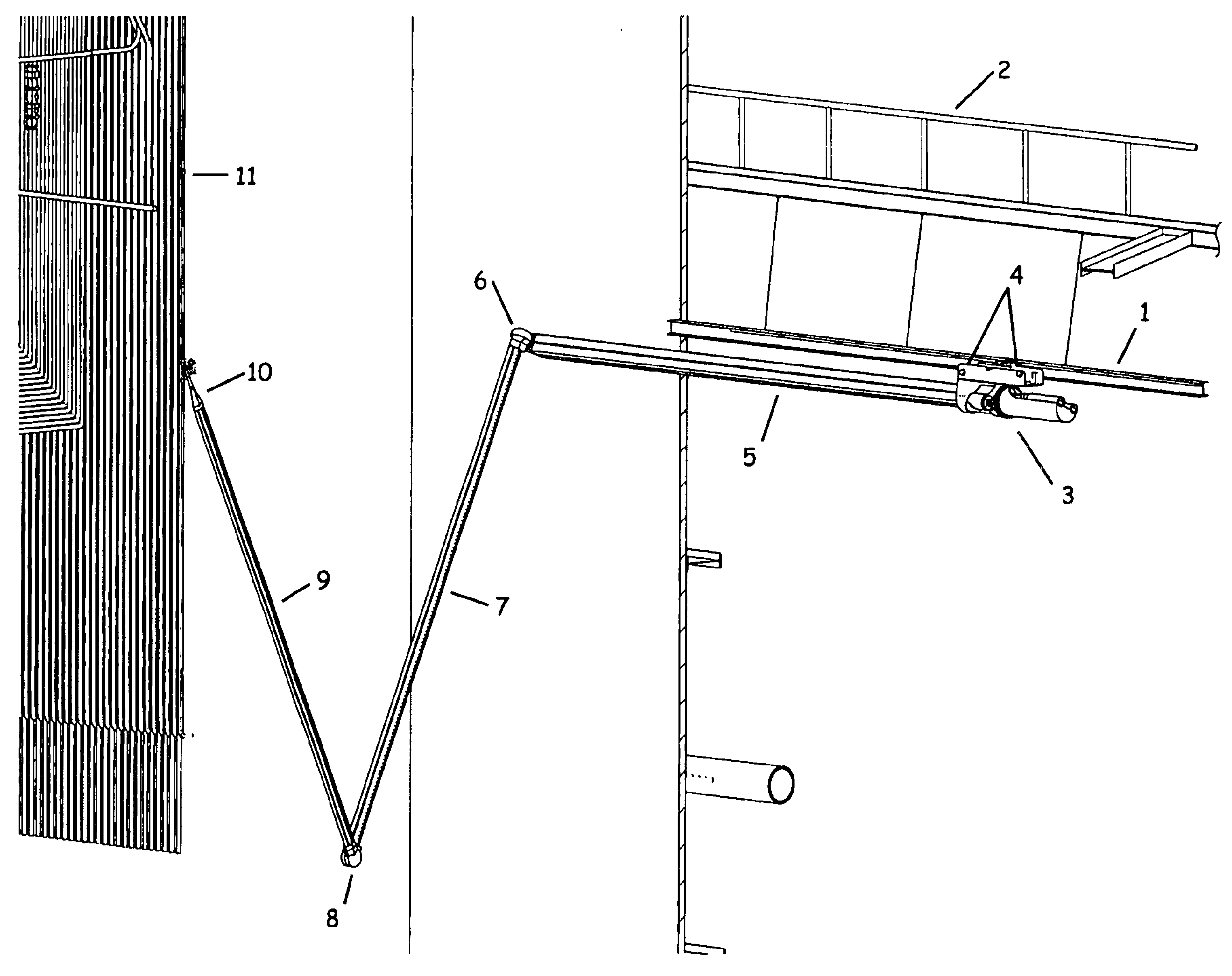
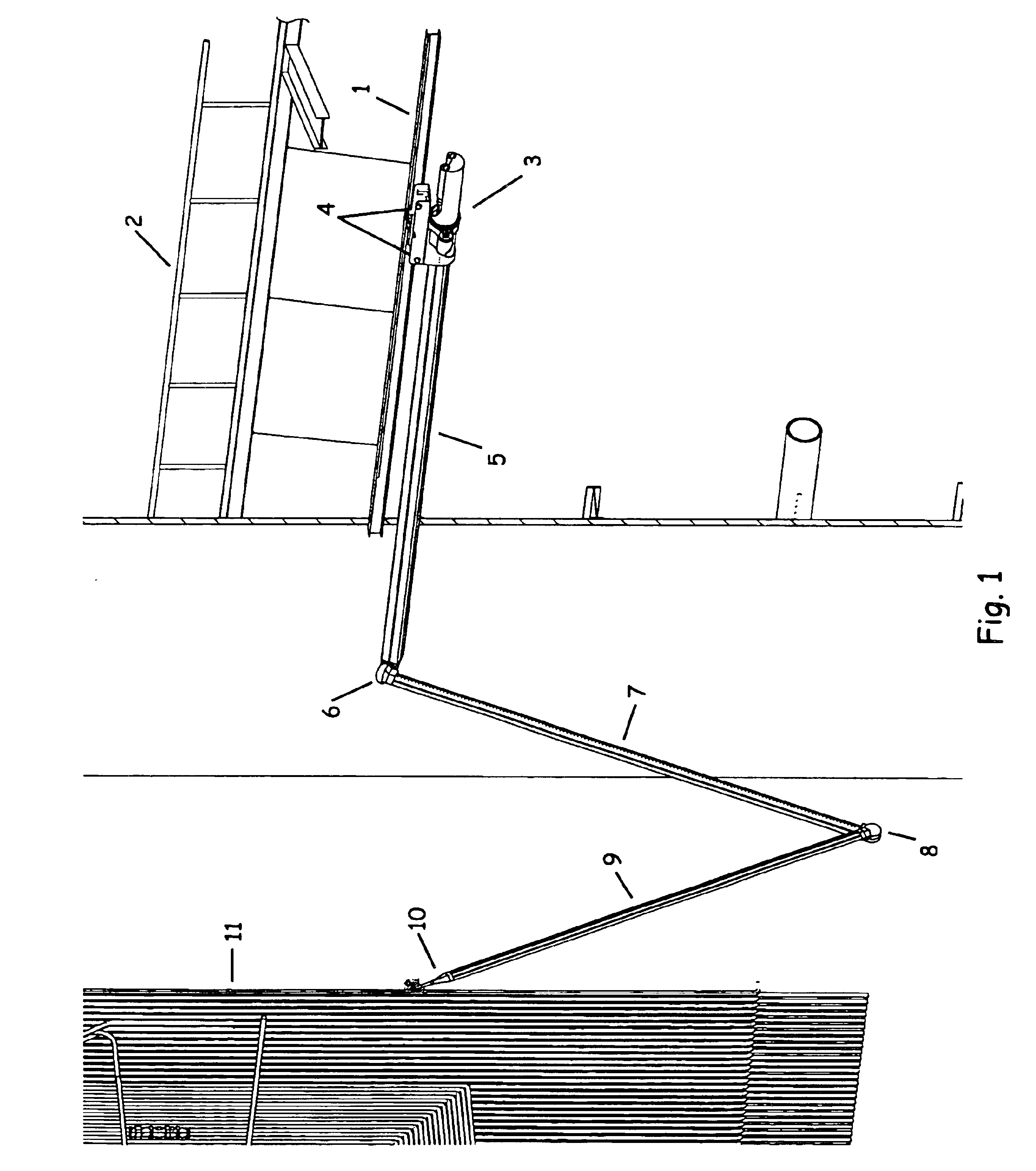
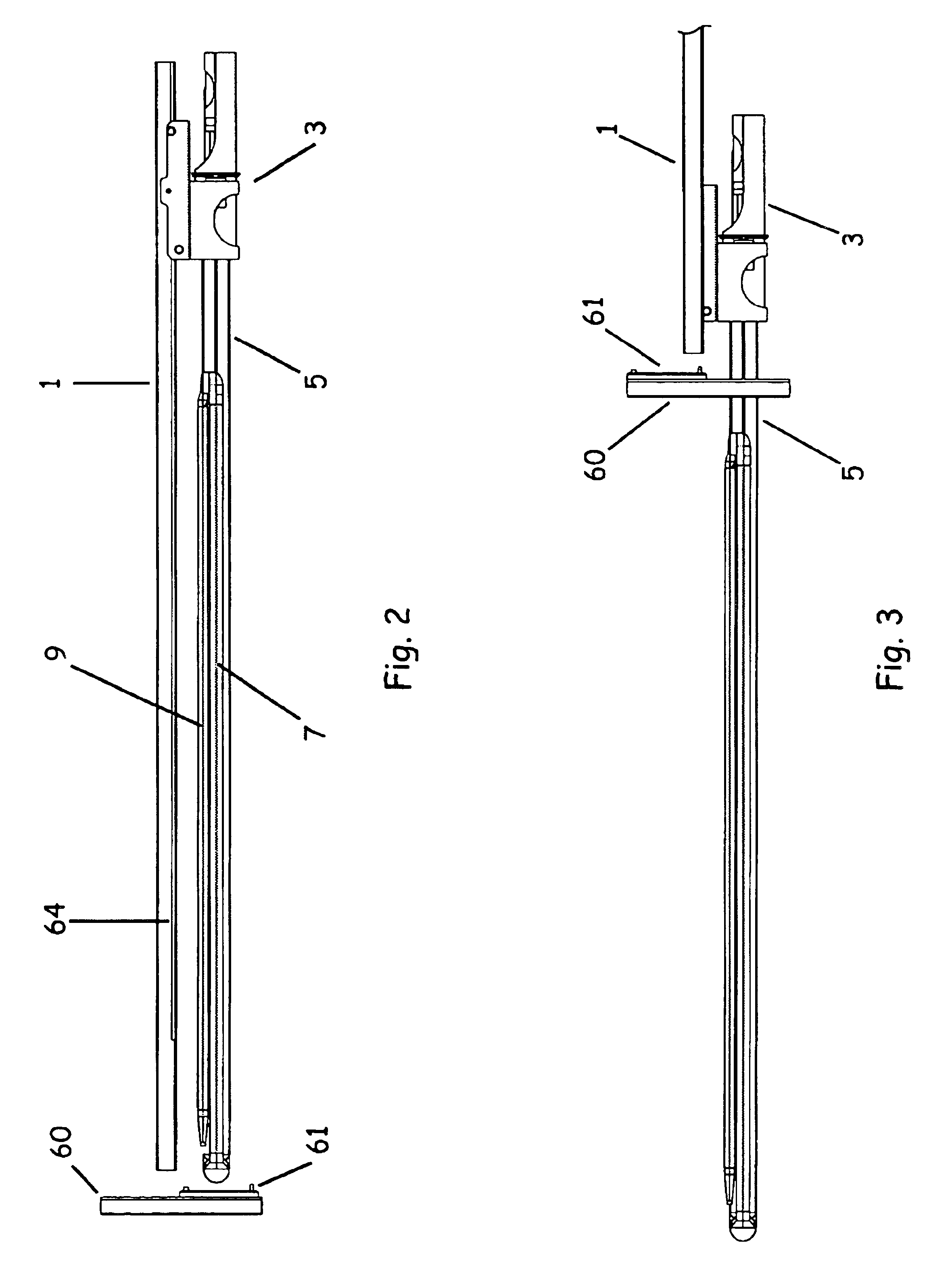
[0032]Referring initially to FIG. 1, a boiler cleaning system employing generally the concepts of the present invention is shown schematically. An external linear mounting rail 1 is to be permanently or temporarily attached to existing boiler support structural framework of the boiler 2. Traversing carriage 3 is fitted to linear mounting rail 1 so as to traverse by motorized control the length of linear mounting rail 1. Bearing wheels 4 are closely fitted to minimize the lash, or slop, of traversing carriage 3 to rail 1, so as to minimize deflections of the subsequent mounting apparatus under conditions of high moment creation. Ultra-lightweight main mast assembly 5 is fitted into traversing carriage 3, so as to allow precise rotation and control of the rotational position of main mast assembly 5. Details of the mechanism to accomplish this are presented later in this specification. Fitted to the opposite end of main mast assembly 5 is rotational shoulder joint 6, to which is additi...


PUM


Abstract

A robotic apparatus for the cleaning and maintenance of coal fired boilers, which is designed to operate in the high temperature environment of the combustion gasses to effectively clean and remove slag deposits of the boiler heat transfer surfaces by use of a precision directed, low pressure, low flow rate water stream. The robotic cleaning apparatus is comprised of lightweight carbon fiber structural elements, attached to the exterior of the boiler, and cooled by annular pressurized water sheaths impingent on a thin metal skin covering the lightweight structural elements. Multiple articulated joints allow for complete access to the heat transfer surfaces of the boiler. A variety of payloads can be delivered to specific points within the boiler, including imaging systems, cutting, and welding apparatuses. A mathematical state space control matrix allows for optimal positioning and feedback control of motions.

Description

FIELD OF THE INVENTION[0001]The present invention relates to electric power generation, power plant maintenance, and, more particularly, to maintain coal fired boilers, and to remove slag from boilers in steam generation plants, and to reduce boiler damage and boiler cleaning down time.BACKGROUND OF THE INVENTION[0002]Coal fire generation plants use a boiler containing closely placed tubes. For more efficient heat exchange, and power generation, the tubes need to remain relatively clean. Clean tubes allow for better heat exchange across the tubes, which cause more efficient power generation. Additionally, heat transfer tubes require repair and maintenance, due to the extreme nature of the combustion, chemical, and metallurgical processes involved in the production of high pressure, high temperature steam.[0003]During operation of power plants, and particularly coal-fired plants, the heat exchange tubes become coated with slag. Current methods and apparatuses to clean the slag requir...

Claims


Application Information

Patent Timeline
Patent Type & Authority Patents(United States)
IPC IPC(8): F22B37/20F22B37/48F28G1/16
CPCF22B37/48F28G1/166F28G15/003
Inventor JOHNSON, SAMUEL A.JOHNSON, DANIEL S.
Owner KURION INC
Why Eureka
Try Eureka