Implantable medical device construction using a flexible substrate

US7211884B1Inactive Publication Date: 2007-05-01PACESETTER INC

Image

  • Implantable medical device construction using a flexible substrate
  • Implantable medical device construction using a flexible substrate
  • Implantable medical device construction using a flexible substrate

Examples


Embodiment Construction

[0042]The following description is of the best mode presently contemplated for practicing the invention. This description is not to be taken in a limiting sense but is made merely for the purpose of describing the general principles of the invention. The scope of the invention should be ascertained with reference to the issued claims. In the description of the invention that follows, like numerals or reference designators will be used to refer to like parts or elements throughout.

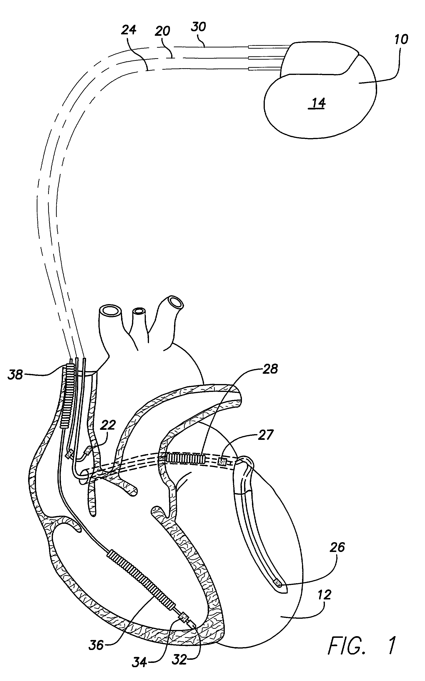
[0043]As illustrated in FIG. 1, a simplified diagram is shown of the multi-chamber implantable stimulation device 10, which is capable of treating both fast and slow arrhythmias with stimulation therapy, including cardioversion, defibrillation, and pacing stimulation. While a particular multi-chamber device is shown, this is for illustration purposes only, and one of skill in the art could readily duplicate, eliminate or disable the appropriate circuitry in any desired combination to provide a device capabl...


PUM


Abstract

A high density electronic circuit for use in an implantable stimulation device that comprises a flexible substrate that has the advantage of integrating “chip-and-wire” microelectronic circuits and flexible interconnections that are adapted to conform to the body compatible housing into a single structure. The flexible substrate has die attach pads, each die attach pad having a set of wire bond pads therearound, each wire bond pad being connected to conductors formed within the substrate according to circuit function. A plurality of chip-and-wire integrated circuit (IC) chips are mounted by epoxy die attachment on the die attach pads, each IC chip has a plurality of contact pads formed on a top surface thereof, and gold wire bonds electrically connect the plurality of contact pads to the wire bonds pads. The wire bonds include a primary bond and, optionally, a safety bond for reinforcement. Other techniques are disclosed to enable the use of the gold wire bonds on a flexible substrate.

Description

FIELD OF THE INVENTION[0001]The present invention relates generally to implantable medical devices, such as implantable cardiac pacemakers, cardioverters, defibrillators, infusion pumps, and the like, and more particularly to a complex implantable medical device that utilizes a flexible substrate as the main chip-carrying substrate and that requires a very high density construction for a plurality of integrated circuit chips.BACKGROUND OF THE INVENTION[0002]Although the present invention will be described with particular reference to implantable cardioverters-defibrillators, it is to be appreciated that the invention has applications with respect to high density electronic component packaging for many other applications that require ultra-high density and high reliability in a small package.[0003]Modern ICD's, for example, are designed to be implanted into the human body to provide pacing stimulation pulses and high voltage shocks to the heart. Such ICD's typically include a hermeti...

Claims


Application Information

Patent Timeline
01 May 2007
Publication
US7211884B1
IPC
H01L23/02
CPC
A61B5/0031; A61N1/3758; H01L23/057; H01L23/13; H01L23/5386; H01L23/5387; H01L25/0652; H01L25/0657
Inventors
DAVIS, DION F.; MOUCHAWAR, GABRIEL A.