Lithography laser with beam delivery and beam pointing control

a beam pointing control and laser technology, applied in the field of lithography lasers with beam pointing control, can solve the problems of large and complex laser systems composed of two separate systems, large and complex to build and operate, and limited commercial application of these two chamber laser systems. the effect of increasing the number of laser beams

Inactive Publication Date: 2007-06-12
CYMER INC
View PDF81 Cites 15 Cited by
  • Summary
  • Abstract
  • Description
  • Claims
  • Application Information

AI Technical Summary

Benefits of technology

[0009](4) a beam monitor for monitoring pulse energy, wavelength and bandwidth of output pulses with a feedback control system for controlling pulse energy, energy dose and wavelength on a pulse-to-pulse basis.
[0010]During the 1989-2001 period, output power of these lasers has increased gradually and beam quality specifications for pulse energy stability, wavelength stability and bandwidth have become increasingly tighter. Operating parameters for a popular lithography laser model used widely in integrated circuit fabrication include pulse energy at 8 mJ, pulse rate at 2,500 pulses per second (providing an average beam power of up to about 20 watts), bandwidth at about 0.5 pm full width half maximum (FWHM) and pulse energy stability at + / −0.35%.
[0011]A well-known technique for reducing the bandwidth of gas discharge laser systems (including excimer laser systems) involves the injection of a narrow band “seed” beam into a gain medium. In some of these systems a laser producing the seed beam called a “master oscillator” is designed to provide a very narrow bandwidth beam in a first gain medium, and that beam is used as a seed beam in a second gain medium. If the second gain medium functions as a power amplifier, the system is referred to as a master oscillator, power amplifier (MOPA) system. If the second gain medium itself has a resonance cavity (in which laser oscillations take place), the system is referred to as an injection seeded oscillator (ISO) system or a master oscillator, power oscillator (MOPO) system in which case the seed laser is called the master oscillator and the downstream system is called the power oscillator. Laser systems comprised of two separate systems tend to be substantially more expensive, larger and more complicated to build and operate than comparable single chamber laser systems. Therefore, commercial application of these two chamber laser systems has been limited.
[0012]For integrated circuit fabrication the lithography machine is typically located separate from the lithography laser light source. The separation is typically 2 to 20 meters. The laser and the lithography machine may be located in separate rooms. A typical practice is to locate the laser in a room one floor below the lithography machine. The laser beam is ultraviolet at wavelengths of about 248 nm for KrF lasers, 193 nm for ArF lasers and 157 nm for F2 lasers. Ultraviolet light especially at the shorter wavelengths of the ArF and F2 lasers is absorbed by oxygen, therefore it is a well known practice to enclose the laser beam path between the laser and the lithography machine and to purge the enclosure with a gas such as nitrogen which provides much lower beam attenuation than air. Included within the enclosure also are a variety of optical components, including mirrors and lenses, for directing the laser beam to a desired beam entrance port in the lithography machine and for providing any needed modification to the beam, such as changes in cross-sectional profile. The equipment for delivering the laser beam to the lithography machine is called a beam delivery unit or “BDU” for short. In the past the BDU has typically been designed and supplied separate from the laser light source.
[0013]What is needed is a better laser design for a pulse gas discharge laser for operation at repetition rates in the range of about 4,000 pulses per second or greater, providing laser light at the entrance port of the lithography machine having beam quality parameters including wavelength, bandwidth, pulse energy, beam pointing angle, beam position and cross-sectional profile needed by the lithography machine.
[0014]The present invention provides a modular high repetition rate ultraviolet gas discharge laser light source with a beam delivery to a production line machine. The system includes an enclosed and purged beam path with beam pointing control for delivery the laser beam to a desired location such as the entrance port of the production line machine. Preferred embodiments include equipment for beam attenuation, equipment for automatic feedback beam alignment and equipment for accurate optics module positioning at installation and during maintenance. In preferred embodiments, the production line machine is a lithography machine and two separate discharge chambers are provided, one of which is a part of a master oscillator producing a very narrow band seed beam which is amplified in the second discharge chamber. This MOPA system is capable of output pulse energies approximately double the comparable single chamber laser system with greatly improved beam quality. A pulse stretcher more than doubles the output pulse length resulting in a reduction in pulse power (mJ / ns) as compared to prior art laser systems. This preferred embodiment is capable of providing illumination at a lithography system wafer plane which is approximately constant throughout the operating life of the lithography system, despite substantial degradation of optical components.

Problems solved by technology

These excimer lasers, when used for integrated circuit lithography, are typically operated in an integrated circuit fabrication line “around-the-clock” producing many thousands of valuable integrated circuits per hour; therefore, down-time can be very expensive.
Laser systems comprised of two separate systems tend to be substantially more expensive, larger and more complicated to build and operate than comparable single chamber laser systems.
Therefore, commercial application of these two chamber laser systems has been limited.

Method used


Image

  • Lithography laser with beam delivery and beam pointing control
  • Lithography laser with beam delivery and beam pointing control
  • Lithography laser with beam delivery and beam pointing control

Examples


first preferred embodiment

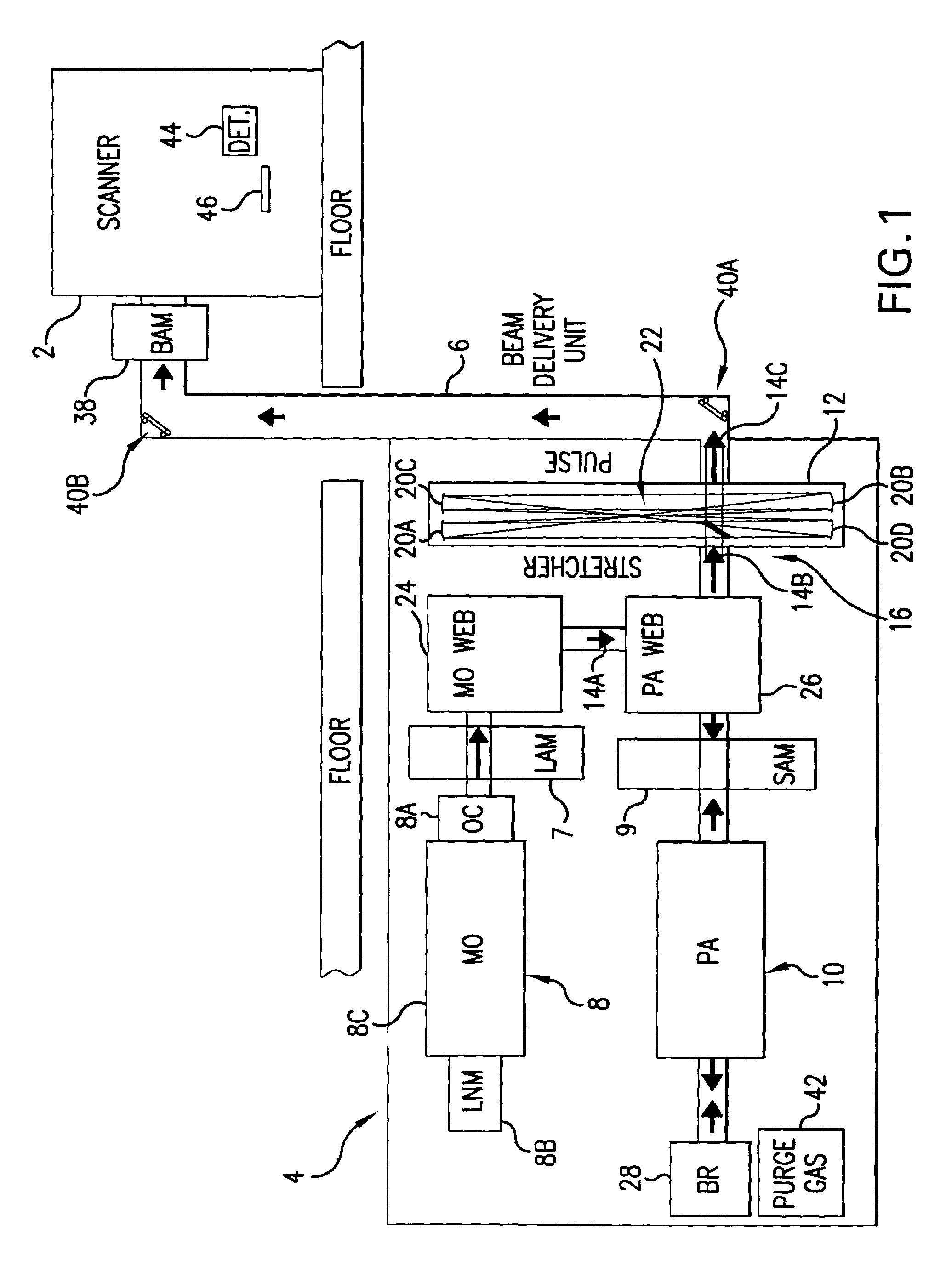
[0034]A first preferred embodiment of the present invention is shown in FIG. 1. In this embodiment a 193 nm ultraviolet laser beam is provided at the input port of a scanner lithography machine 2 such as the one of those supplied by Canon or Nikon with facilities in Japan or ASML with facilities in the Netherlands. In this case the main components of the laser system 4 are installed below the deck on which the scanner is installed. This preferred embodiment includes a MOPA laser system with special relay optics, a pulse stretcher and a beam delivery unit 6 which provides an enclosed beam path for delivering the laser beam to the input port of the scanner. The beam delivery unit includes equipment for beam attenuation, automatic beam alignment with feedback control and special alignment features for component alignment during installation and maintenance.

Mopa

[0035]This particular laser system includes a master oscillator 8 and a power amplifier 10 and is a type of laser system known ...


PUM

PropertyMeasurementUnit
charging voltageaaaaaaaaaa
voltage electrical potentialaaaaaaaaaa
wavelengthsaaaaaaaaaa

Abstract

The present invention provides a modular high repetition rate ultraviolet gas discharge laser light source with a beam delivery to a production line machine. The system includes an enclosed and purged beam path with beam pointing control for delivery the laser beam to a desired location such as the entrance port of the production line machine. Preferred embodiments include equipment for beam attenuation, equipment for automatic feedback beam alignment and equipment for accurate optics module positioning at installation and during maintenance. In preferred embodiments, the production line machine is a lithography machine and two separate discharge chambers are provided, one of which is a part of a master oscillator producing a very narrow band seed beam which is amplified in the second discharge chamber. This MOPA system is capable of output pulse energies approximately double the comparable single chamber laser system with greatly improved beam quality. A pulse stretcher more than doubles the output pulse length resulting in a reduction in pulse power (mJ/ns) as compared to prior art laser systems. This preferred embodiment is capable of providing illumination at a lithography system wafer plane which is approximately constant throughout the operating life of the lithography system, despite substantial degradation of optical components.

Description

[0001]The present invention is a continuation-in-part of Ser. No. 10 / 255,806 filed Sep. 25, 2002 now U.S. Pat. No. 6,704,340, Ser. No. 10 / 233,253 filed Aug. 30, 2002 now U.S. Pat. No. 6,704,339, Ser. No. 10 / 141 / 216 filed May 7, 2002 now U.S. Pat. No. 6,693,939, Ser. No. 10 / 036,676, filed Dec. 21, 2001 now U.S. Pat. No. 6,882,674, Ser. No. 10 / 036,727 filed Dec. 21, 2001 now U.S. Pat. No. 6,865,210, Ser. No. 10 / 006,913 filed Nov. 29, 2001, now U.S. Pat. No. 6,535,531, Ser. No. 10 / 000,991 filed Nov. 14, 2001 now U.S. Pat. No. 6,795,474, Ser. No. 09 / 943,343, filed Aug. 29, 2001 now U.S. Pat. No. 6,567,450, Ser. No. 09 / 854,097, filed May 11, 2001 now U.S. Pat. No. 6,757,316, Ser. No. 09 / 848,043, filed May 3, 2001, now U.S. Pat. No. 6,549,551, Ser. No. 09 / 837,150 filed Apr. 18, 2001, now U.S. Pat. No. 6,504,860, and Ser. No. 09 / 829,475 filed Apr. 9, 2001 now U.S. Pat. No. 6,765,945, and claims the benefit of Provisional Ser. No. 60 / 443,673 filed Jan. 28, 2003, all of which are incorporate...

Claims


Application Information

Patent Timeline
Patent Type & Authority Patents(United States)
IPC IPC(8): H01S3/22G21G5/00H01L21/027G02B26/08G02B27/09G03F7/20H01LH01L21/00H01S3/00H01S3/034H01S3/036H01S3/04H01S3/041H01S3/0971H01S3/10H01S3/13H01S3/134H01S3/136H01S3/137H01S3/223H01S3/225H01S3/23
CPCG02B26/0816G02B27/0972G03F7/70025G03F7/70041G03F7/70058G03F7/7055H01S3/005H01S3/0057H01S3/225H01S3/2333H01S3/036H01S3/041H01S3/0971H01S3/136H01S3/137H01S3/2366H01S3/2308
Inventor DAS, PLASH P.WEBB, R. KYLEGIOVANARDI, MARCOFRANCIS, GREGORYDORN, HUCKLEBERRY B.ERLANDSEN, KYLE P.NELSON, JOHN W.SANDSTROM, RICHARD L.ERSHOV, ALEXANDER I.
Owner CYMER INC
Why Eureka
Try Eureka