Fluorescence imaging endoscope

a fluorescence imaging and endoscope technology, applied in the field of laser-induced fluorescence imaging endoscopes, can solve the problems of significant parallax between the white light image of the ccd and the fluorescence image of the optics module, and achieve the effect of perfect registration of these two images, simplified system design, and higher total image resolution

Inactive Publication Date: 2007-06-26
MASSACHUSETTS INST OF TECH +1
View PDF50 Cites 101 Cited by
  • Summary
  • Abstract
  • Description
  • Claims
  • Application Information

AI Technical Summary

Benefits of technology

[0008]In this particular embodiment, the CCD has a resolution of 270×328 pixels and an objective lens of 2.5 mm in diameter. The images are collected in 33 ms in RGB format. The advantages of this particular embodiment include that the in vitro fluorescence images exhibit a signal-to-noise ratio (SNR) of about 34 at clinical working distances of 20 mm (distance between tip of endoscope and tissue surface), which is superior to that obtained using the UV Module/CID detector, which has a SNR of about 18 at the same distance. The use of the CCD eliminates the need for the optics module and greatly simplifies system design. In addition, it also avoids problems associated with the tendency of the UV module to rotate in the biopsy channel. By...

Problems solved by technology

Parallax between the white light image of the CCD and the f...

Method used


Image

  • Fluorescence imaging endoscope
  • Fluorescence imaging endoscope
  • Fluorescence imaging endoscope

Examples


Embodiment Construction

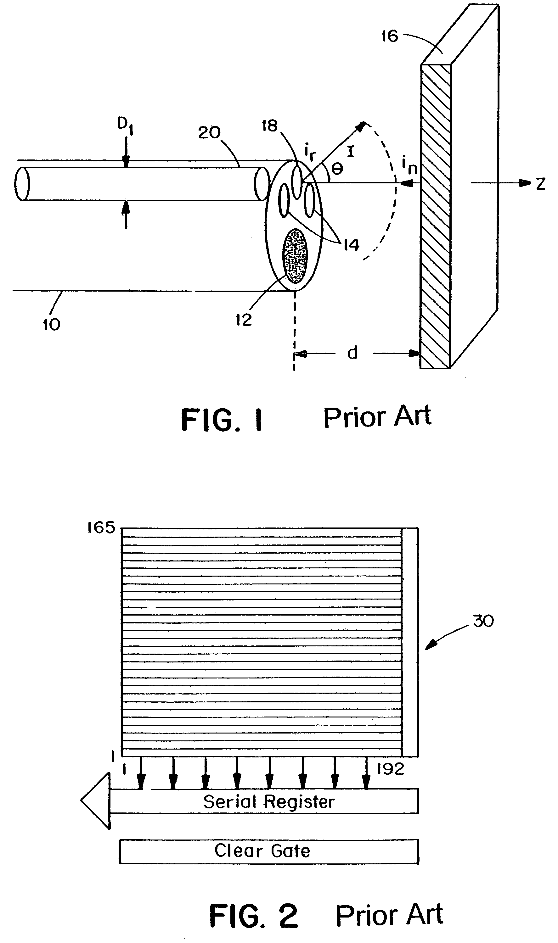
[0026]The equations describing the number of signal photons, Ns, collected by a given pixel in an endoscope as a function of the separation distance d and the radial distance ρ on the tissue surface, and the corresponding SNR are as follows:

[0027]Ns⁡(p)=ηs⁢λem⁢g2⁢Tf⁢Ti⁢To⁢fp⁢rL2⁢ɛt⁡(λem,Δ⁢⁢λ)⁢tan⁢⁢θm2⁢Po⁡(λex)⁢Δ⁢⁢thc⁢⁢8⁢(1-cos⁢⁢θm)⁢Nf⁢d2⁡(1+(pd)2)3.5SNR=NsNs+(σeG)2⁢(1)

The geometry and certain symbols are defined in FIG. 1. Note also the emission wavelength λem, pixel array size g×g, fiber optic transmission efficiency Ti, the bandwidth of the filtered emission wavelength Δλ, the fraction of the transmitted energy in this wavelength region Tf, the collective efficiency To of the system optics including the long pass filter, lens and eyepiece, incident light energy Po(λex)Δt,h is Planck's constant, c is the speed of light, fp is the packing fraction of the fiber cores εt is the quantum efficiency of the tissue, and Nf is the total number of resolution elements. The signal to noise rat...


PUM


Abstract

An endoscope having an optical guide that is optically coupled to a first broadband light source and a second laser light source that emits light at a wavelength in a range of 350 nm to 420 nm. The endoscope has an image sensor at a distal end and collects a reflectance image including red, green and blue components with the image sensor in response to illumination by said broadband light source. The image sensor also collects an autofluorescence image having a blue component, a green component and a red component. A processor processes the fluorescence image by determining a ratio of the fluorescence image and the reflectance image to provide a processed fluorescence image.

Description

CROSS REFERENCES TO RELATED APPLICATIONS[0001]This application is a continuation application of U.S. patent application Ser. No. 09 / 238,664, filed Jan. 26, 1999, now U.S. Pat. No. 6,537,211, which claims the benefit of U.S. Provisional Application No. 60 / 072,455 filed on Jan. 26, 1998, the entire contents of which is incorporated herein by reference.GOVERNMENT SUPPORT[0002]The invention was supported, in whole or in part, by grant numbers CA53717, P41RR02954, and DK 39512 from National Institutes for Health. The Government has certain rights in the invention.BACKGROUND OF THE INVENTION[0003]The following relates to the development of a laser-induced fluorescence imaging endoscope for mapping cancerous or precancerous tissues in hollow organs. In initial clinical studies, on colon polyps, Ultraviolet (UV) light was used at 370 nm to excite visible fluorescence (400-700 nm), the spectral signatures of which enabled differentiating between normal and abnormal tissues. Previously endosc...

Claims


Application Information

Patent Timeline
IPC IPC(8): A61B1/04A61B1/06A61B10/00A61B1/00A61B1/05A61B1/07A61B5/00
CPCA61B1/00009A61B1/043A61B5/0071A61B5/0084A61B5/415A61B5/418G01J3/02G01J3/0232G01J3/10G01J3/4406G01N21/6456A61B1/0005A61B1/05A61B1/07G01N2021/6417G01N2021/6421G01N2021/6484A61B1/000094
Inventor WANG, THOMAS D.FELD, MICHAEL S.WANG, YANGDAM, JACQUES VANFULGHUM, STEPHEN F.
Owner MASSACHUSETTS INST OF TECH
Why Eureka
Try Eureka