
Multiple sampling device and method for investigating biological systems

a biological system and sampling device technology, applied in the field of multiple sampling devices and methods, can solve the problems of significant impact of sample preparation errors, disruption of the chemical balance of the chemical inside the animal, and time-consuming and laborious problems

Inactive Publication Date: 2007-08-21
PAWLISZYN JANUSZ B +2
View PDF19 Cites 70 Cited by
  • Summary
  • Abstract
  • Description
  • Claims
  • Application Information

AI Technical Summary

Benefits of technology

[0010]It is an object of the present invention to obviate or mitigate at least one disadvantage of previous devices and methods for evaluating components of interest in biological systems.

Problems solved by technology

This method produces accurate results with high specificity for the compound of interest, but is time consuming and labour intensive.
Also, because of the large number of steps in the process there is a significant chance of errors in sample preparation impacting the results.
This method has good sensitivity and selectivity and accuracy for the target compounds but is limited in that the chemical balance the chemicals exist in inside the animal is disrupted during sampling.
In many cases this disruption reduces the value of the results obtained, and in some cases makes this technique inappropriate for the analysis.
Where the blood volume removed is a high proportion of the total blood volume of the animal, as is commonly the case when mice are used, the death of the animal results.
The main limitations of this type of device are that they normally respond to a spectrum of chemicals rather than having specificity for only one chemical.
Sensors are also susceptible to interferences where another chemical present in a system interferes with the response produced by the target chemicals.
For these reasons biosensors are normally limited in terms of accuracy and precision.
The first is the desire to study chemical processes in association with the normal biochemical milieu of a living system, and the second is the lack of availability or impracticality frequently associated with size of removing suitable samples for study from the living system.
The current commercial devices do, however, have some limitations for in vivo analysis inside a living animal.
The overall dimension of the current device is typically too large for direct in vivo analysis and for direct interfacing to microanalytical systems, the time required for the LC extraction phase to come into equilibrium with chemicals in a sample is relatively long (typically 1 hr or more in a well-stirred sample) and analysis is sensitive to degree of convection in the sample.
Also the present SPME devices cannot be conveniently coupled to positioning devices necessary for in-vivo investigation at a well-defined part of the living system.

Method used


Image

  • Multiple sampling device and method for investigating biological systems
  • Multiple sampling device and method for investigating biological systems
  • Multiple sampling device and method for investigating biological systems

Examples


example 1

Polypyrrole Coating on Stainless Steel Wires and Use in a Biological System

[0210]Stainless steel wires (grade T-304V, 0.005″) were from Small Parts Inc. (Miami Lakes Fla.). Lithium perchlorate (95%) and pyrrole (98%) were from Sigma / Aldrich (Mississauga, ON). Pyrrole was used as received for one month after opening, was stored refrigerated and the bottle was layered with nitrogen after each use. Polypyrrole (PPY) films were deposited onto the supporting electrode surface (stainless steel wire) by anodic oxidation of the pyrrole monomer in the presence of an aqueous electrolyte solution (counter ion). A potentiostat / galvanostat (Model 273, EG&G Princeton Applied Research) was used for the electrodeposition. The last 15 mm of the wires were coated potentiostatically at 0.8 V for 20 minutes. The placement of a silicon septum 15 mm from the end of the wire allowed for accurate control of coating length. The coating solution used was pyrrole (0.1M) and lithium perchlorate (0.1M) in water...

example 2

MALDI Analysis

[0221]In this Example, a medical aerosol compressor was used as the matrix sprayer, and 10 mg / mL matrix DHB solution was deposited into the nebulizer vial. After analyte extraction the fiber tip was placed 1.5 cm above the nebulizer vial, and by turning on the compressor very fine drops of the matrix DHB solution were formed and attached to the fiber tip. The 800 μm fiber was tested with the spray method for a 0.05 mg / mL TOAB sample solution. The times for matrix application were set at 45 seconds and 30 seconds, respectively, considering the lower analyte concentration. Two 3 minute air-dry times were applied before and after the spray of matrix.

[0222]FIG. 27 shows an IMS spectrum from this analysis. The limit of detection was found to be 0.02 mg / mL with S / N ˜2. This level is 10 times lower than the previous 0.2 mg / mL established by the 400 μm fiber using the pre-mixed method. The sensitivity has been increased dramatically. This great improvement was attributed to th...

example 3

On-Fiber and In-Needle Laboratory

[0224]In micromachined devices, controlling flow is not simple since it requires pumps or electroosmontic flow means. In addition it is quite difficult to mix analytes in the small channels. A more efficient approach is to do sample processing on the surface or in thin layers adjacent to the surface. The structures chosen in this Example are the outer surfaces of fibers. Alternatively, the inside surface of a tube fiber could be used. This Example makes use of a small fiber to demonstrate a convenient sampling method to collect analytes from small objects. In this work capillary electrophoresis with fluorescence detection has been used to facilitate detection of small amounts of analytes extracted by the fiber.

[0225]Chemicals and materials. 4-fluoro-7-nitro-2,1,3-benzoxadiazole (NBD-F) was purchased from Fluka (Sigma-Aldrich Canada Ltd., Oakville, Ontario). Brij35® and all amino acids (glycine, L-phenylalanine, L-proline, L-glutamate and L-aspartate)...


PUM

PropertyMeasurementUnit
thicknessesaaaaaaaaaa
timeaaaaaaaaaa
diameteraaaaaaaaaa

Abstract

Multiwell plate applications are describe for use with a plurality of fibres having an extraction phase coated thereon in combination with a positioning device. The device and method described are able to perform adsorption of components of interest from a biological system in high volume.

Description

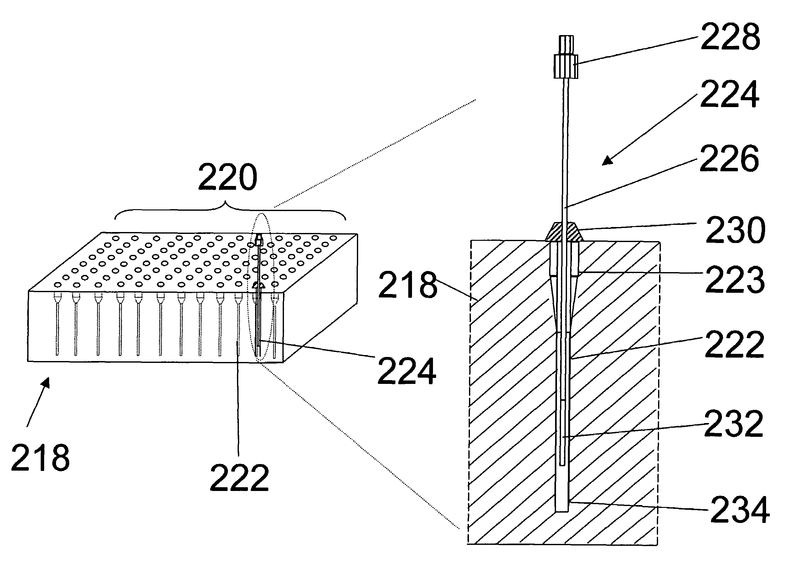
[0001]This application is a continuation-in-part of U.S. patent application Ser. No. 10 / 506,827, filed Sep. 7, 2004, derived from International Patent Application PCT / CA2003 / 0000311 filed Mar. 6, 2003. Further, this application is entitled to the benefit of and claims priority to U.S. Patent Application 60 / 364,214 filed Mar. 11, 2002; U.S. Patent Application 60 / 393,309 filed Jul. 3, 2002; U.S. Patent Application 60 / 421,001, filed Oct. 25, 2002; U.S. Patent Application 60 / 421,510 filed Oct. 28, 2002; and U.S. Patent Application 60 / 427,833 filed Nov. 21, 2002. Additionally, this application is entitled to the benefit of and claims priority to U.S. Patent Application 60 / 604,631 filed Aug. 27, 2004. The entirety of each document is incorporated herein by reference.FIELD OF THE INVENTION[0002]The present invention relates generally to multiple sampling devices and methods for quantifying or identifying components of interest in a biological system, such as in an animal.BACKGROUND OF THE ...

Claims


Application Information

Patent Timeline
Patent Type & Authority Patents(United States)
IPC IPC(8): G01N1/18C12M1/34C12M3/00C23C16/52G01N21/00G01N31/22B01L11/00B01L3/00B01L9/00B05D1/12B05D7/22B32B5/02A61B5/145B01L99/00G01N1/00G01N1/34G01N30/00G01N35/02G01N35/10H01J49/16
CPCA61B5/417A61B10/0045B01L3/5025G01N1/405H01J49/0431A61B5/14514A61B5/14Y10T436/255A61B17/3403B01L2300/046B01L2300/069B01L2300/0829B01L2300/0838G01N35/028G01N2001/4016G01N2030/009G01N2030/062G01N2035/1053Y10T436/25375A61B5/150022A61B5/15003A61B5/150099A61B5/150229A61B5/150389A61B5/150503A61B5/151A61B5/153
Inventor PAWLISZYN, JANUSZ B.LORD, HEATHER L.MUSTEATA, MARCEL
Owner PAWLISZYN JANUSZ B
Learn More