
Electron gun for producing incident and secondary electrons

a technology of incident and secondary electrons and electron guns, applied in the field of electron guns, can solve the problems of short-duration pulse development of high-current, electron-generating pulses, and other problems

Inactive Publication Date: 2007-10-23
MAKO FREDERICK MICHAEL +1
View PDF0 Cites 3 Cited by
  • Summary
  • Abstract
  • Description
  • Claims
  • Application Information

AI Technical Summary

Benefits of technology

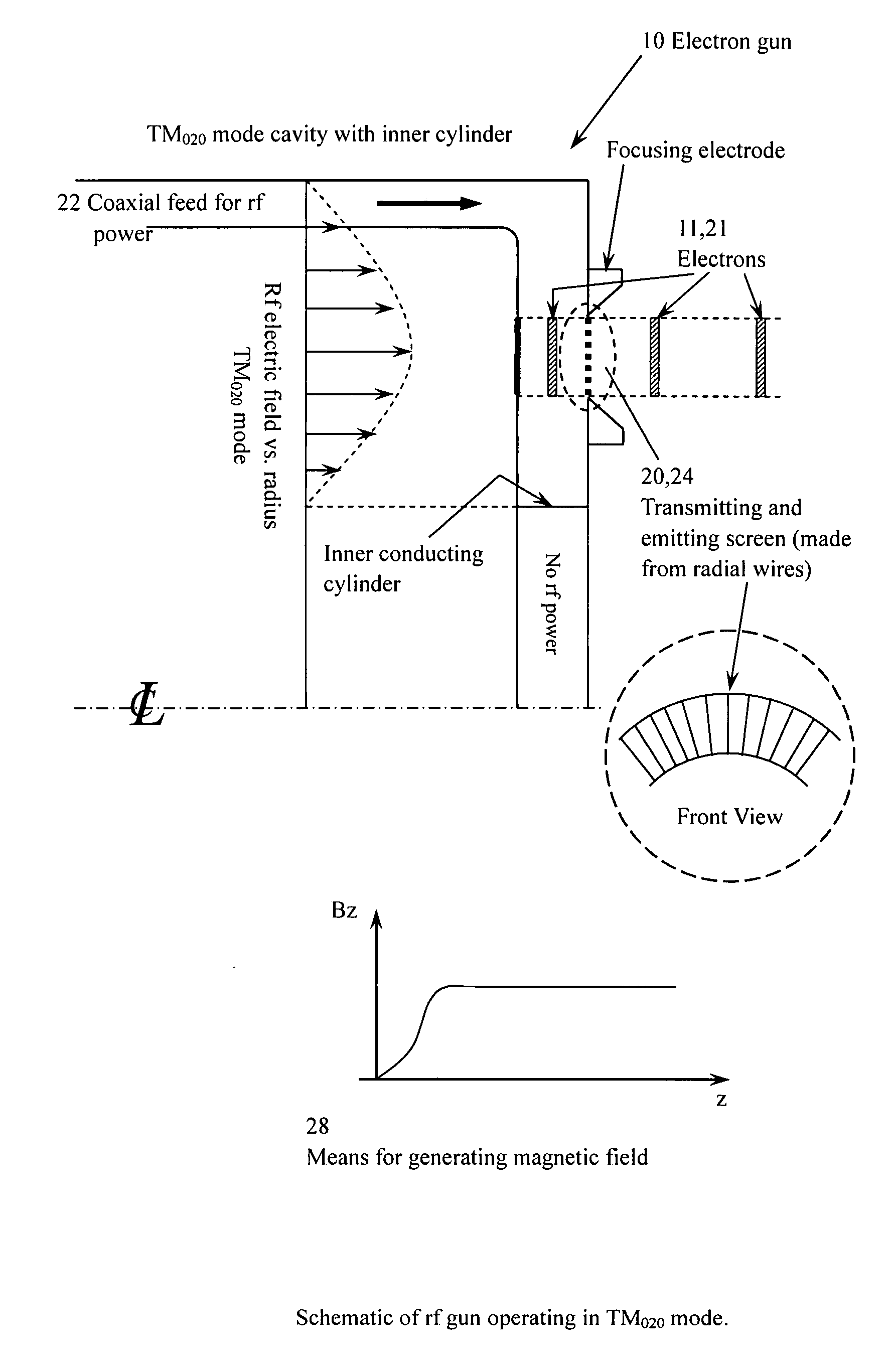
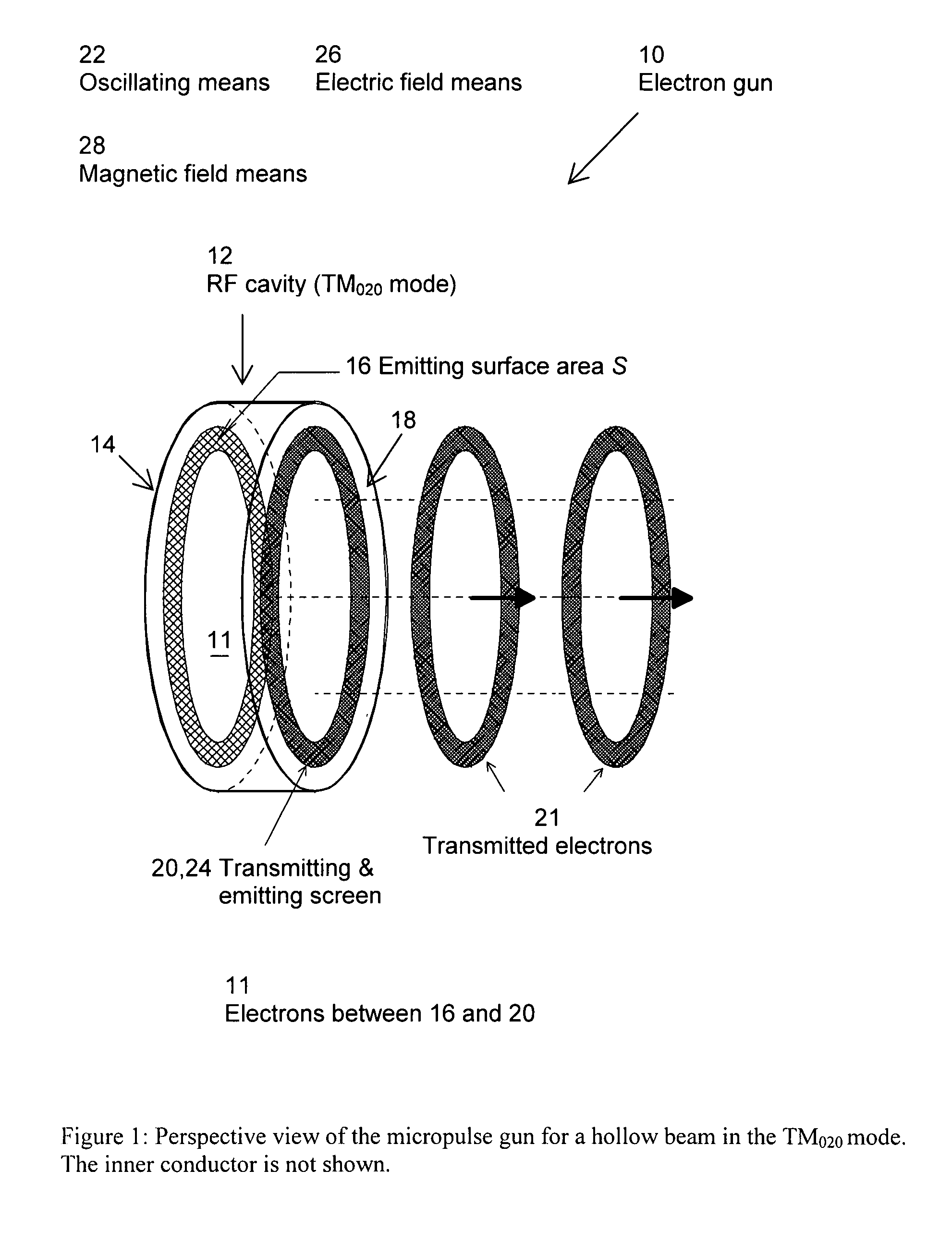
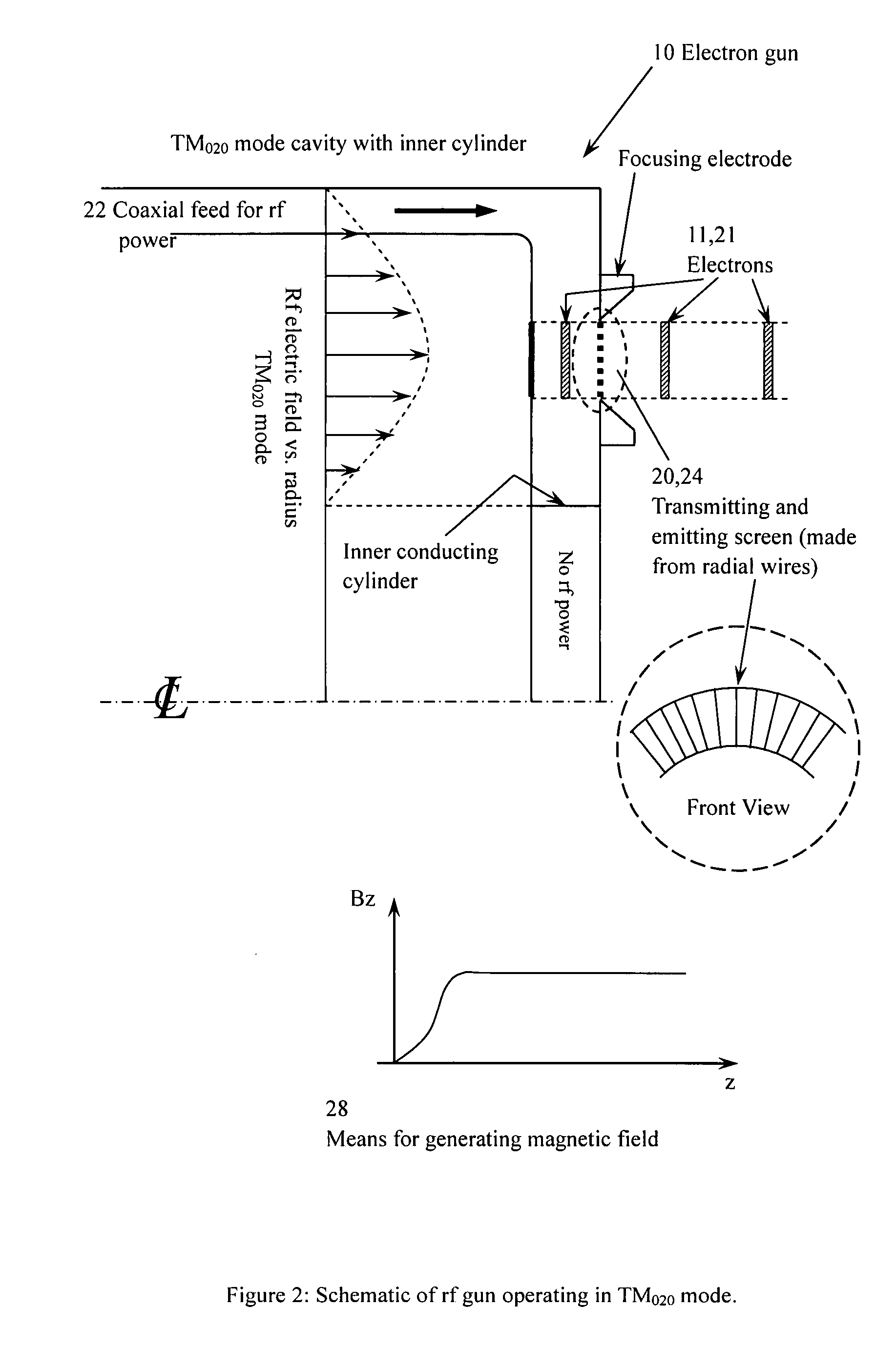
[0007]Micro-pulses or bunches are produced by resonantly amplifying a current of secondary electrons in an rf cavity. Bunching occurs rapidly and is followed by saturation of the current density within ten rf periods. The “bunching” process is not the conventional method of compressing a long beam into a short one, but results by selecting particles that are in phase with the rf electric field, i.e., resonant. One wall of the cavity is highly transparent to electrons but opaque to the input rf field. The transparent wall allows for the transmission of the energetic electron bunches and serves as the cathode of a high-voltage injector. FIG. 1 shows a perspective view of the micropulse gun emitting electron-bunches in an annular geometry. Axial and radial expansion of the pulse is minimized outside the cavity by using rapid acceleration and a combination of electrostatic and magnetic focusing. Inside the cavity, radial expansion is controlled by electric and / or magnetic fields. Both analytic theory and PIC simulation verify this concept. This micro-pulse electron gun should provide a high peak power, multi-kiloampere, picosecond-long electron source which is suitable for many applications. Of particular interest are: high energy picosecond electron injectors for linear colliders, free electron lasers and high harmonic rf generators for linear colliders, or super-power nanosecond radar.

Problems solved by technology

The development of high-current, short-duration pulses of electrons has been a challenging problem for many years.

Method used


Image

  • Electron gun for producing incident and secondary electrons
  • Electron gun for producing incident and secondary electrons
  • Electron gun for producing incident and secondary electrons

Examples


Embodiment Construction

[0059]Referring now to the drawings wherein like reference numerals refer to similar or identical parts throughout the several views, and more specifically to FIG. 1 thereof, there is shown an electron gun 10. The electron gun 10 comprises an RF cavity 12 having a first side 14 with an emitting surface 16 and a second side 18 with a transmitting and emitting section 20. The gun 10 is also comprised of a mechanism 22 for producing an oscillating force which encompasses the emitting surface 16 and the section 20 so electrons 11 are directed between the emitting surface 16 and the section 20 to contact the emitting surface 16 and generate additional electrons 11 and to contact the section 20 to generate additional electrons 11 or escape the cavity 12 through the section 20 giving the transmitted electrons 21.

[0060]The section 20 preferably isolates the cavity 12 from external forces outside and adjacent the cavity 12. The section 20 preferably includes a transmitting and emitting scree...


PUM


Abstract

An electron gun. The electron gun includes an RF cavity having a first side with an emitting surface and a second side with a transmitting and emitting section. The gun also includes a mechanism for producing an oscillating force which encompasses the emitting surface and the section so electrons are directed between the emitting surface and the section to contact the emitting surface and generate additional electrons and to contact the section to generate additional electrons or escape the cavity through the section. A method for producing electrons.

Description

[0001]This is a continuation application of U.S. patent application Ser. No. 08 / 348,040 filed Dec. 1, 1994 now abandoned.FIELD OF THE INVENTION[0002]The present invention is related to electron guns. More specifically, the present invention is related to an electron gun that uses an RF cavity subjected to an oscillating electric field.BACKGROUND OF THE INVENTION[0003]The development of high-current, short-duration pulses of electrons has been a challenging problem for many years. High-current pulses are widely used in injector systems for electron accelerators, both for industrial linacs as well as high-energy accelerators for linear colliders. Short-duration pulses are also used for microwave generation, in klystrons and related devices, for research on advanced methods of particle acceleration, and for injectors used for free-electron-laser (FEL) drivers.[0004]The difficulty of generating very high-current pulses of short duration can be illustrated by examination of a modern lina...

Claims


Application Information

Patent Timeline
Patent Type & Authority Patents(United States)
IPC IPC(8): H01J25/76G09G1/04H01J3/02H01J23/06
CPCH01J23/06H01J3/023
Inventor MAKO, FREDERICK MICHAELPETER, WILLIAM KALMAN
Owner MAKO FREDERICK MICHAEL
Learn More