Systems and methods for actively-peaked current-mode logic

a current-mode logic and active-peaked technology, applied in the field of circuits, can solve the problems of low integration level, high power consumption of bipolar designs, and low level of integration, and achieve the highest integration level, less cost, and low power consumption.

Active Publication Date: 2007-10-30
MICROSEMI STORAGE SOLUTIONS
View PDF2 Cites 31 Cited by
  • Summary
  • Abstract
  • Description
  • Claims
  • Application Information

AI Technical Summary

Benefits of technology

[0040]A method and apparatus for creating high speed logic circuits in a CMOS environment using current steering logic cells with actively-peaked NMOS or PMOS loads and the biasing of these logic cells is disclosed. The logic cells can include, for example, buffers, AND gates, OR gates, flip-flops, and latches. The current steering cells with actively-peaked loads can provide one or more advantages over conventional logic cells. For example, embodiments can provide one or more of: reduced power consumption, smaller chip area, and higher speed over conventional logic cells. In one embodiment, this performance boost is at least partially achieved using NMOS followers with resistively degenerated gates to create frequency peaked transfer function of current-mode logic cells. Embodiments can advantageously be applied to virtually any situation in which relatively good power area and performance are desired for state machine logic, parallel to serial conversions, serial to parallel conversions and more.

Problems solved by technology

However, typical bipolar designs have high power usage and a low level of integration.
It consumes only a small amount of area.
However, it has the drawback that it is relatively slow from what is required in the industry today.
The issue with this method of logical function is that the PMOS devices generally need to be sized large than the NMOS transistors because of the fact that the mobility in PMOS (μp) is significantly lower than in the NMOS (μn).
The capacitance of a CMOS gate is large and the larger devices cause additional loading.
CMOS logic has high noise margin due to a static path that restores correct logic state in the presence of noise.
This large swing means it requires large amounts of voltage noise to switch logic states.
However, it has severe speed limitations that prevent its usage in many high-speed applications.
This extreme variation can lead to difficulties in optimizing of the circuit parameters.
This is a significant issue, since the output parasitic capacitance, which directly effects the speed of the cells, has a large dependence on the size of the differential pair (MP / MN).
Advantageously, the large gain variation limits the minimum transistor size of the differential pair.
Although the operating speeds are much faster than conventional CMOS logic, current-mode logic is still limited in operating frequencies.
The speed limitation comes from the parasitic capacitance on the output and the resistor load.
However, these cells have significant gain variation over process, voltage and temperature and do not have a bandwidth high enough to handle many of the high-speed applications in leading edge designs.
Spiral inductors used in implementations of the passive inductor loads consume a relatively large area on silicon.
Since the area of the inductor eventually becomes severely restrictive, this places limitations on the smallest possible tail current applicable for the CML buffer with inductive broadbanding 610.
Larger tail currents lead to larger power consumption of the CML.
The similar gain variation leads to the same type of gain related issues as seen with the purely resistive CML buffer without inductive broadbanding 600.
For example, the gain variation can render it relatively difficult to select a circuit device size for relatively high operating speeds.
However, the CML buffer with inductive broadbanding 610 consumes relatively large amounts of area and power and is limited by the same gain variation issues that are seen with the purely resistive CML buffer without inductive broadbanding 600.

Method used


Image

  • Systems and methods for actively-peaked current-mode logic
  • Systems and methods for actively-peaked current-mode logic
  • Systems and methods for actively-peaked current-mode logic

Examples


Embodiment Construction

Introduction and Overview

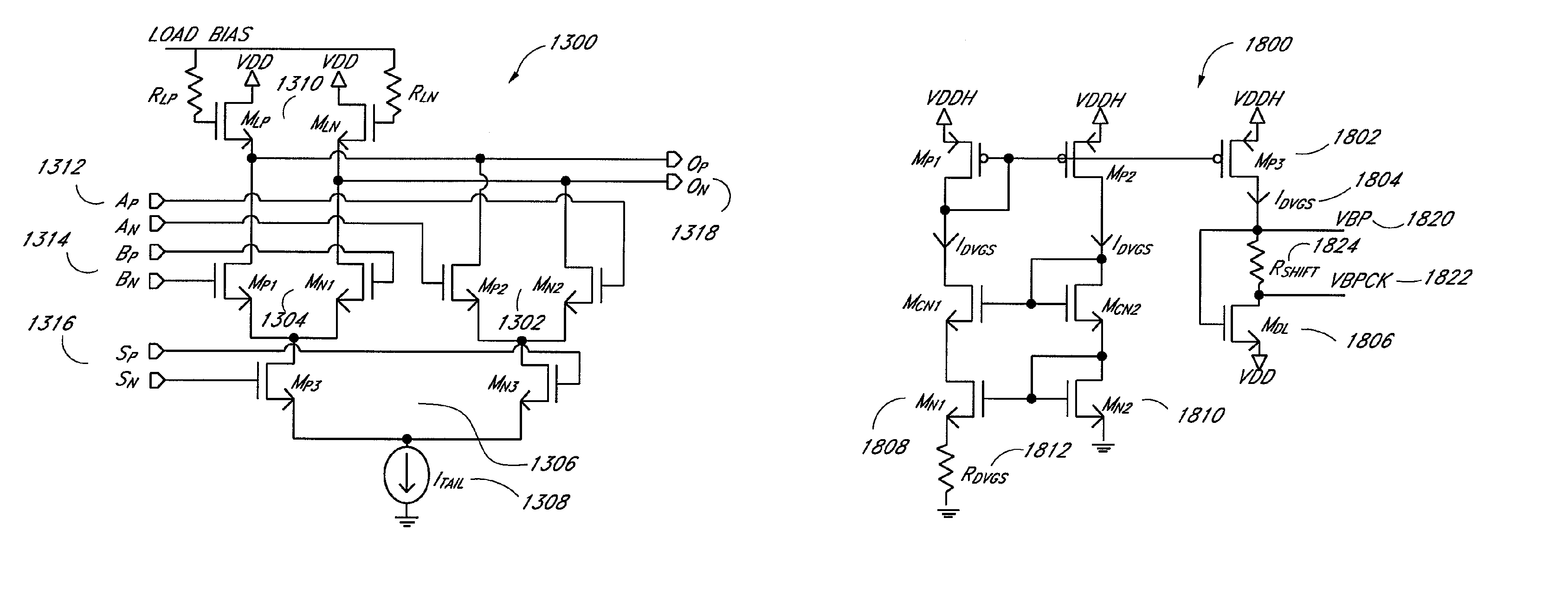
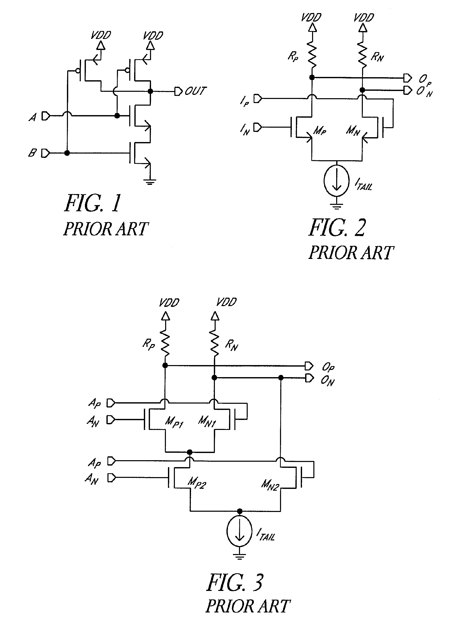
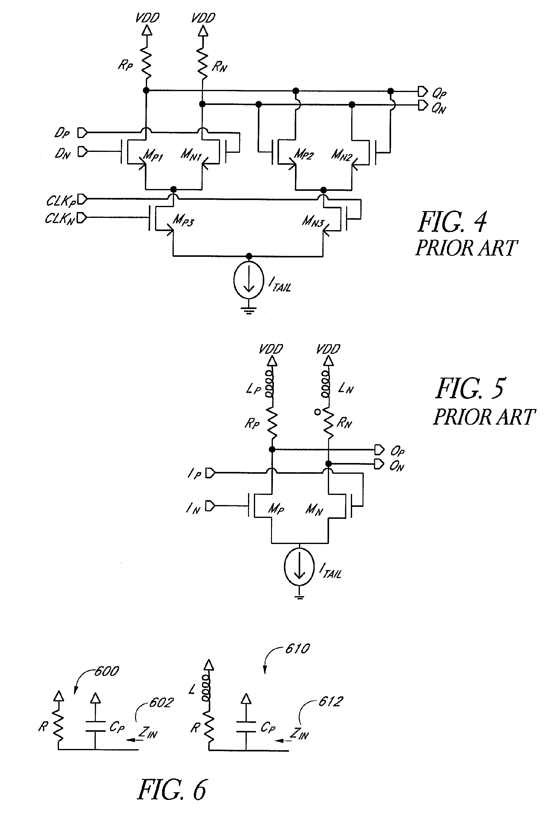
[0080]FIG. 8 illustrates one embodiment of a structure for an actively-peaked current mode logic buffer 800. This logic buffer 800 can be compared with the conventional devices described earlier in connection with FIG. 2 and FIG. 5. As with the conventional devices, a current source 802 drives a differential pair 804, 806. However, the actively-peaked current mode logic buffer 800 is loaded with NMOS transistors 808, 810 with resistors 812, 814 in series with the gates and a special bias 816 for the gates of the NMOS device loads. These NMOS loads 808, 810 are configured in a voltage follower mode that have particular benefits to a high-speed logic family.

[0081]These NMOS device loads 808, 810 can be combined to create many different logic structures. These logic structures include an “OR” gate, an “AND” gate, a Mux, and a D-type flip flop. These structures can be created using a combination of differential pairs with the NMOS voltage follower load.

[0082]The...


PUM


Abstract

A method and apparatus for creating high speed logic circuits in a CMOS environment using current steering logic cells with actively-peaked NMOS or PMOS loads and the biasing of these logic cells is disclosed. The logic cells can include, for example, buffers, AND gates, OR gates, flip-flops, and latches. The current steering cells with actively-peaked loads can provide benefits such as reduced power consumption, smaller area, and higher speed performance over conventional devices. This performance boost is preferably achieved using NMOS followers with resistively degenerated gates to create frequency peaked transfer function of current-mode logic cells. These logic cells with actively-peaked loads can advantageously be used in circuits in which relatively good power area and performance are desired for state machine logic, parallel to serial conversions, serial to parallel conversions, and the like.

Description

RELATED APPLICATION[0001]This application is a continuation application of U.S. application Ser. No. 10 / 820,381, filed Apr. 8, 2004 now U.S. Pat. No. 7,202,706, which claims the benefit under 35 U.S.C. § 119(e) of U.S. Provisional Application No. 60 / 462,089, filed Apr. 10, 2003, the disclosures of each of which are hereby incorporated by reference in their entireties herein.FIELD OF THE INVENTION[0002]The invention generally relates to circuits. In particular, the invention relates to relatively-high speed differential logic circuits.BACKGROUND OF THE INVENTION[0003]Engineers have approached the problem of processing digital signals at high frequencies over the last three decades. Typically the industry has been working with two types of transistor processes to deal with digital logic functions: bi-polar and Complementary Metal Oxide Semiconductors (CMOS). The bipolar process provides higher processing speeds due to the inherent ability of bipolar circuits to operate faster. However...

Claims


Application Information

Patent Timeline
Patent Type & Authority Patents(United States)
IPC IPC(8): H03K19/20H03K19/094
CPCH03K19/01707H03K19/09432H03K19/01728
Inventor PLASTERER, JOHN P.LYE, WILLIAM MICHAELMCADAM, MATTHEW W.
Owner MICROSEMI STORAGE SOLUTIONS
Why Eureka
Try Eureka