

Protective sheet for solar battery module, method of fabricating the same and solar battery module
- Summary
- Abstract
- Description
- Claims
- Application Information
AI Technical Summary
Benefits of technology
Problems solved by technology
Method used
Image

Examples
second embodiment
[0275]Protective sheets for solar battery modules, and solar battery modules in a second embodiment according to the present invention will be described with reference to FIGS. 1 to 9 which have been used for describing the first embodiment.
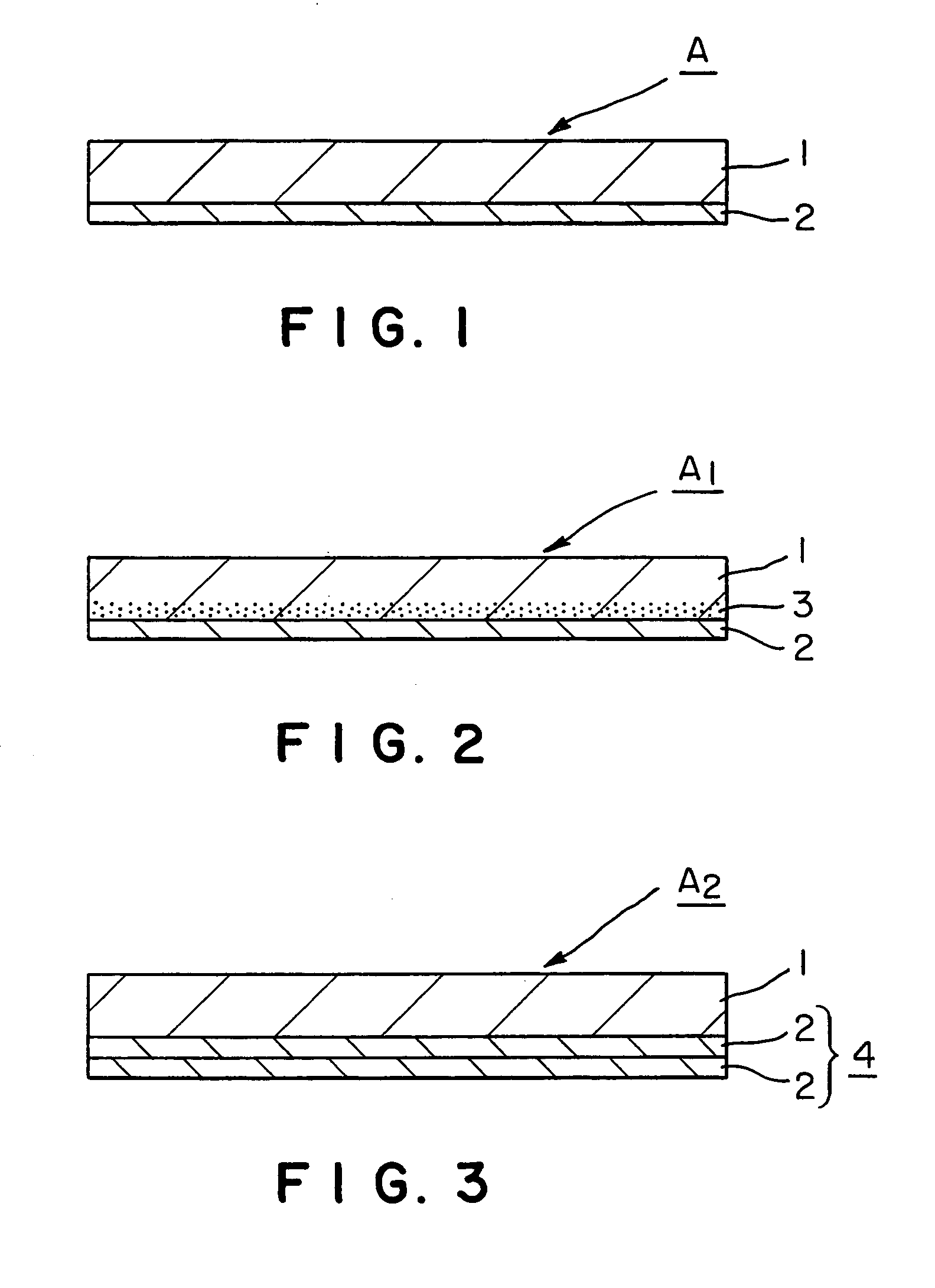
[0276]Referring to FIG. 1, a protective sheet A in accordance with the present invention for a solar battery module has a basic structure constructed by forming a deposited inorganic oxide thin film 2 on one of the surfaces of a weather-resistant sheet 1 of a cyclic polyolefin resin.
[0277]As shown in FIG. 3, a protective sheet A1 in an example of the present invention for a solar battery module is formed by forming a multilayer film 4 consisting of at least two deposited inorganic oxide thin films 2 on one of the surfaces of a cyclic polyolefin resin sheet 1.
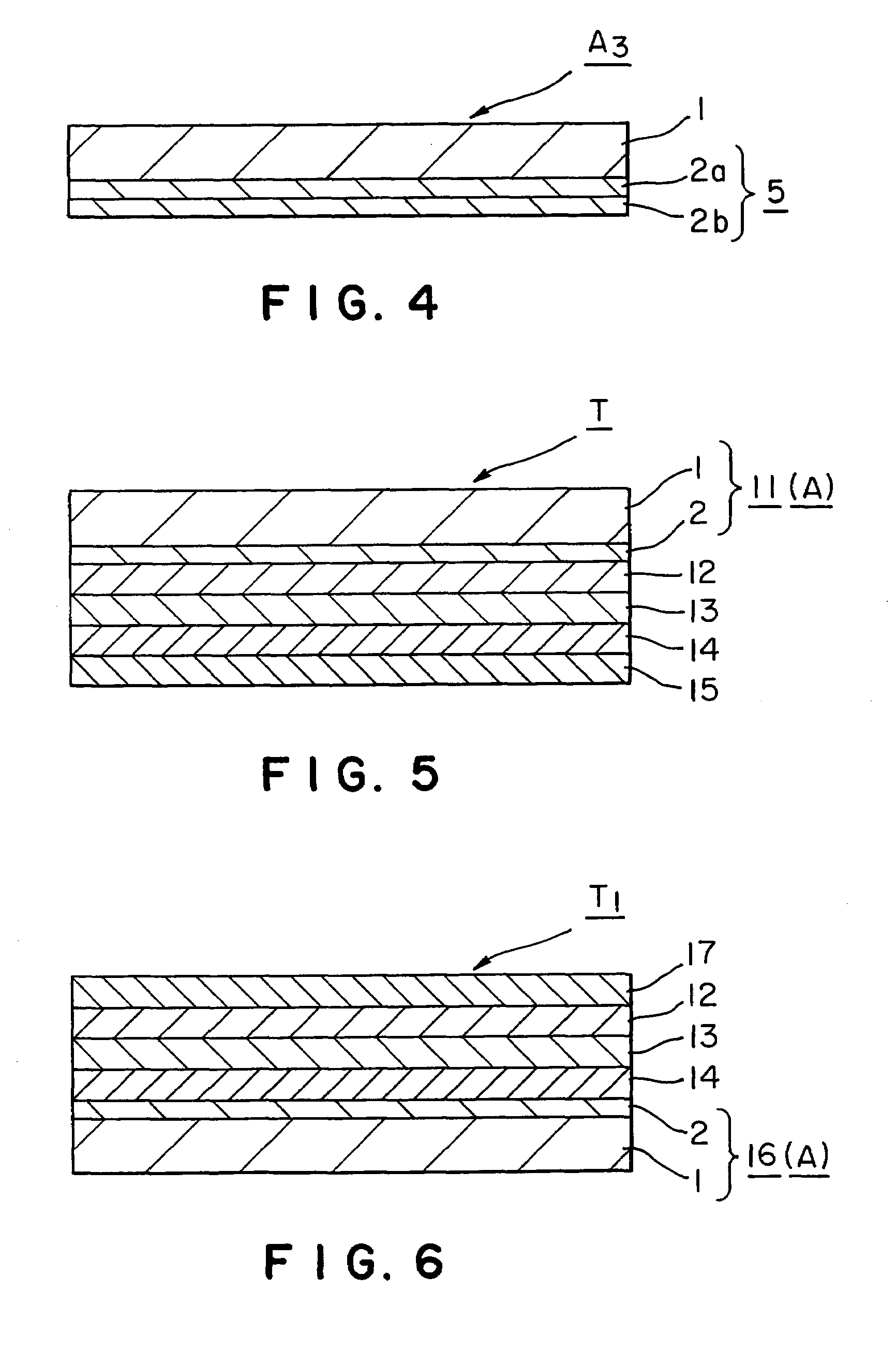
[0278]As shown in FIG. 4 a protective sheet A3 in another example of the present invention for a solar battery module comprises a cyclic polyolefin resin sheet 1 and a composite film 5 formed...
example 16
[0417](1) A protective sheet that is the same as the protective sheet in Example 10 was used as the back surface protective sheet of a solar battery module. The solar battery module was fabricated by superposing a 3 mm thick glass sheet, a 400 μm thick ethylene-vinyl acetate copolymer sheet, a 38 μm thick biaxially oriented polyethylene terephthalate film provided with an array of amorphous silicon solar cells, a 400 μm thick ethylene-vinyl acetate copolymer sheet and the back surface protective sheet in that order with the corona-processed deposited silicon oxide thin film of the back surface protective sheet facing inside and with the surface of the 38 μm thick polyethylene terephthalate film provided with the array of amorphous silicon solar cells facing the 3 mm thick glass sheet, and laminating those component layers by using adhesive layers of an acrylic resin.
[0418](2) A protective sheet in accordance with the present invention and another solar battery module of the same com...
example 17
[0419](1) A protective sheet that is the same as the protective sheet in Example 11 was used as the back surface protective sheet of a solar battery module. The solar battery module was fabricated by superposing a 50 μm thick polyvinyl fluoride sheet (PVF sheet), a 400 μm thick ethylene-vinyl acetate copolymer sheet, a 38 μm thick biaxially oriented polyethylene terephthalate film provided with an array of amorphous silicon solar cells, a 400 μm thick ethylene-vinyl acetate copolymer sheet and the back surface protective sheet in that order with the plasma-processed deposited aluminum oxide thin film of the back surface protective sheet facing inside and with the surface of the 38 μm thick polyethylene terephthalate film provided with the array of amorphous silicon solar cells facing the 50 μm thick polyvinyl fluoride sheet, and laminating those component layers by using adhesive layers of an acrylic resin.
[0420](2) A protective sheet in accordance with the present invention and ano...
PUM
| Property | Measurement | Unit |
|---|---|---|
| Length | aaaaa | aaaaa |
| Length | aaaaa | aaaaa |
| Nanoscale particle size | aaaaa | aaaaa |
Abstract
Description
Claims
Application Information