Systems for the control and use of fluids and particles

a technology of fluids and systems, applied in the field of forming, shaping, controlling and using fluids, fibers and particles, to achieve the effects of facilitating beneficial microbe infection, reducing time and expense of spraying, and high viscosity

Active Publication Date: 2007-12-25
KAMTERTER PROD LLC
View PDF31 Cites 25 Cited by
  • Summary
  • Abstract
  • Description
  • Claims
  • Application Information

AI Technical Summary

Benefits of technology

[0037]In one significant aspect of this invention, droplet size and size distributions of sprayed agricultural inputs to agricultural fields are controlled. For example, viscous agricultural products that would, in prior art practice, be diluted so they are no longer viscous and then sprayed, instead can be sprayed in their viscous form with a drop size that will maximize the usefulness of the droplets. Certain pesticides, for example, that in the prior art are techniques are diluted and sprayed at high cost because of the heavy weight of water carrier that must be carried by spray vehicles and need for frequent replenishing of the supply on the spray vehicles, can be sprayed in a more concentrated form using the equipment and processes of this invention at much lower cost. Moreover, the droplets formed by the prior art equipment are frequently carried by the wind and become an environmental problem. However, with the method and apparatus of this invention, the problem of drift is reduced.
[0052]It can also be understood from the summary of the invention that the method, formulations and apparatus for forming fibers in accordance with this invention has several advantages, such as: (1) longer fibers can be formed; (2) chitosan fibers, mats, sheets and powders can be more economically and better formed; (3) fibers can be formed without electrospinning; and (4) fibers and powders can be formed more efficiently and faster.

Problems solved by technology

Under some circumstances, vehicles used to spray agricultural fields carry large volumes of diluted active ingredients because it is difficult to spray more concentrated forms of the active ingredient.
One reason for diluting the active ingredient is because existing spray equipment used in agriculture cannot spray viscous material with the desired size drops and drop distribution.
The prior art spray apparatuses have several disadvantages such as for example: (1) they require vehicles carrying the agricultural inputs to carry heavier weights of agricultural inputs with the associated water carrier than desirable; (2) they require the replenishment of the supply of agricultural inputs carried by the spray vehicles periodically, thus increasing the time and expense of spraying; (3) they cannot be used for the application of some beneficial microbes because the microbes are killed by the high pressure used in the prior art techniques for application of agricultural inputs; (4) the low viscosity agricultural inputs drift when sprayed; (5) some of the carriers used for dilution, such as water, have high surface tension and form beads on contact rather than spreading such as over a leaf; (6) the sprayed drops tend to break up because of lowered shear resistance, thus forming smaller drops that are subject to increased drift; (7) some of the carriers used for dilution, such as water, have unpredictable mineral content and pH variations; (8) the angle of the cone of sprayed fluid from the nozzles is small thus requiring the nozzle to be positioned at a high elevation to obtain adequate coverage but the high elevation increases drift; (9) the use of some carriers for dilution in some circumstances causes precipitation of active ingredients and (10) the prior art systems cannot effectively spray some particles such as particles that have absorbed active ingredients in them that are to be released at a later time or over a timed interval.
This type of spraying apparatus has not generally been adapted for use in spraying agricultural inputs.
Moreover, the known spraying apparatus for spraying viscous materials is not readily adjustable for different size droplets or particles or viscosity of the droplets and is not equipped with a convenient mechanism to adjust drop size or pattern or viscosity of the drops in the field as appropriate and thus reduce drift by conveniently adjusting drop size and viscosity in accordance with circumstances such as wind speed, height of spraying or speed such as for example by ground vehicle or airplane.
The prior techniques for forming nanofibers have disadvantages in that they are not suitable for forming nanofibers of viscous fluids because the electric potential to adequately draw the viscous fluid is close to the break down potential of air and the system causes corona discharge before the fibers can be formed.
However, conventional chitosan solutions are undesirable for electrospinning because of their high conductivity, viscosity and surface tension.
Other difficulties with putting chitosan in solution are toxicity of some solutions.
While chitosan has long been known to form viscous gels in carboxylic acids such as acetic, formic, and ascorbic acid, as well as in mineral acids, it is not soluble in either water or basic solutions.
In addition, all organic solvents—with the notable exception of a 3 to 1 mixture of dimethyleformamide and dinitrogen tetroxide, and some fluorine-containing solvents, which are both costly and toxic—are also unable to dissolve chitosan regardless of its degree of deacetylation (DA).
However, with the method described in U.S. Pat. No. 6,695,992, only relatively short fibers have been obtained and at times the fibers stick to one another When attempts have been made to keep the fibers separate by magneto dynamic force the fibers stuck to each other rather than being kept separate.
This method has one disadvantage, namely that it is impossible to adjust the rotational speed of the collector to ensure that fibers remain “continuous” i.e. without snapping due to a mismatch between the fiber deposition rate and the bobbin's angular velocity.
However, the use of carbon dioxide was to dissolve the chitosan—not to remove acid and there is no suggestion of using carbon dioxide to remove the acid.
These apparatuses have a tendency to distribute seeds with irregular and poorly controlled spacing between the seeds and under some circumstances damage seeds.
Moreover, they are prone to plugging from the accumulation of seeds in tubes used in the apparatus.
Because the tube-seed ratio must be so large, adequate flow for fluid drilling of large seeds requires inordinate amounts of fluid and very large pumps to get the seeds delivered.
The same limitations apply to piston or air displacement systems.
These disadvantages limit the flexibility of the current fluid drilling hardware for delivering large seeds and for using smaller quantities of gel to reduce gel cost per acre.
Further, this ratio limitation impacts on the use of optimal concentrations of treatment chemicals or microorganisms in gels while still being able to use low total amounts of treatment per acre through using for example, gel to seed ratios of 1 to 1.
Thus the physics of dispensing seeds suspended in non-Newtonian fluids imposes strict limitations on the utility of the current commercial fluid drilling hardware.
This approach has not entirely solved the problem in a satisfactory manner.
This apparatus has a disadvantage of damaging seeds and being relatively complicated and unreliable.
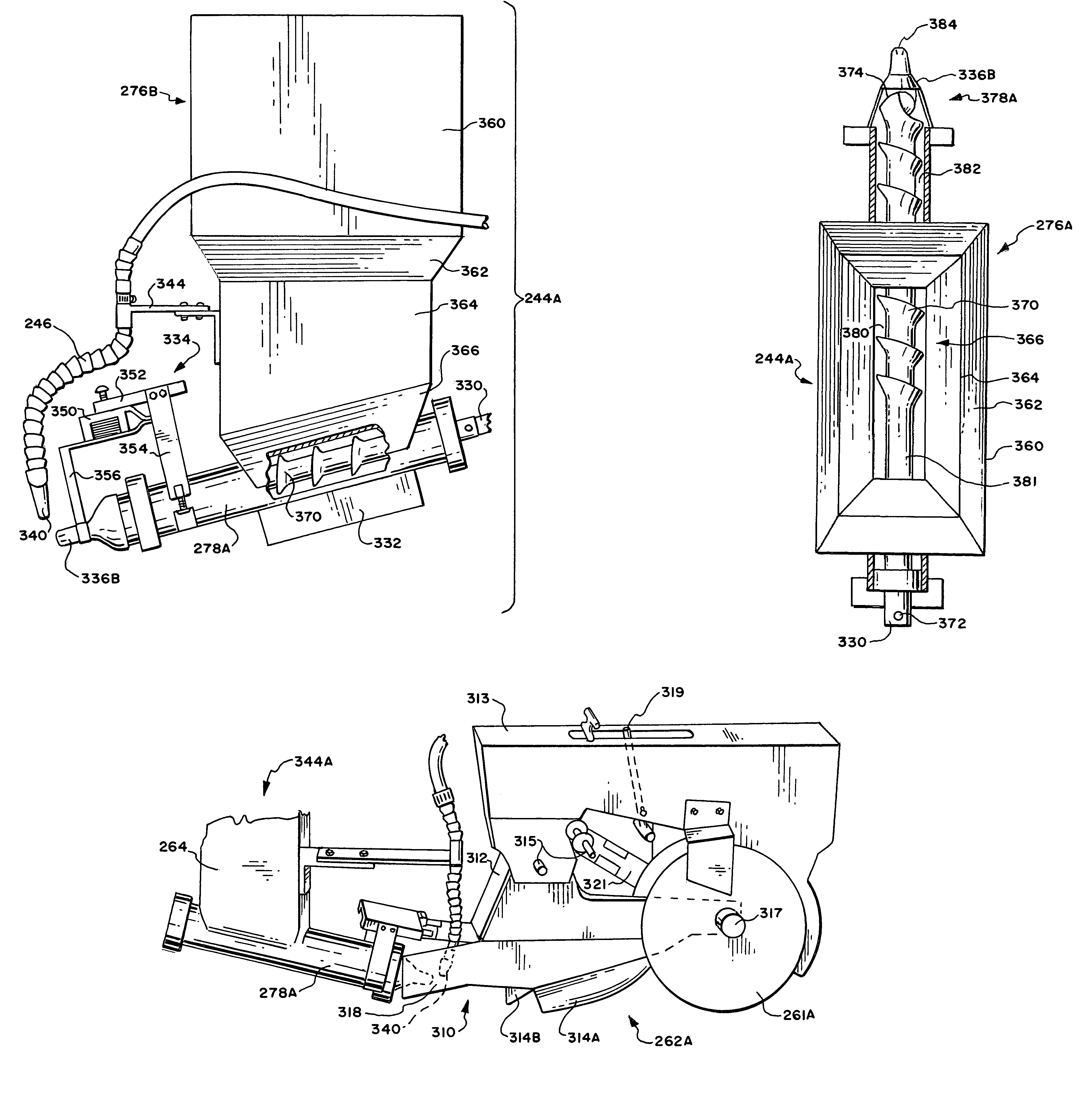
Augers are known for conveying matter from place to place but such augers have not been successfully adapted up to now to fluid drilling apparatuses.
However, this patent does not disclose any method of fluid drilling.
The augers used in the prior art are not designed in a manner adequate to separate seeds, to avoid plugging of the conduits carrying the seeds and gel to the nozzle from which they are to be expelled into the ground nor to maintain spacing between seeds while moving them along the auger.
The prior art planting shoes have a disadvantage when used for fluid drilling in that there is insufficient space to permit accurate deposit of gel and seeds at a location protected by the shoe.
These apparatuses have a disadvantage in that they waste expensive additives by applying them nonuniformly and at locations where they are not needed.
Attempts to innoculate seeds with beneficial microorganisms have not been as successful as desired.

Method used


Image

  • Systems for the control and use of fluids and particles
  • Systems for the control and use of fluids and particles
  • Systems for the control and use of fluids and particles

Examples


example 1

Formation of C02-EtOH-chitosan Solution

[0145]Procedure:[0146]A suspension of chitosan powder (log, Aldrich DA=80.6%) in 300 ml of distilled water was magnetically stirred. a 1 percent Glacial acetic acid (9.53 mL, EM Science, 99.9%) was then added to dissolve the suspended chitosan. After that, ethanol (Pharmco, 200 proof) was added slowly to the solution

[0147]Result:[0148]A few drops of the 1% chitosan / acetic acid solution in ethanol, are enough to yield precipitates and / or for a gel,

example 2

Formation of C02-EtOH-chitosan Solution

[0149]Procedure:[0150]A suspension of chitosan powder (log, Aldrich DA=80.6%) in 300 ml of distilled water was magnetically stirred. Glacial acetic acid (9.53 mL, EM Science, 99.9%) was then added to dissolve the suspended chitosan. The resulting solution was bubbled with carbon dioxide (Linweld, industrial grade) for 30 min. After that, ethanol (Pharmco, 200 proof) was added slowly to the solution while stirring and bubbling CO2 until total solution reached a volume of H L.

[0151]Result:[0152]A clear chitosan solution was produced with no precipitates.

example 3

Formation of C02-MeOH-chitosan Solution

[0153]Procedure:[0154]A suspension of chitosan powder (Vanson, DA=83.3%), in 300 ml of distilled water was magnetically stirred. a 1 percent Glacial acetic acid (9.53 mL, EM Science, 99.9%) was then added to dissolve the suspended chitosan. After that, methanol was added slowly to the solution.

[0155]Result:[0156]A few drops of the 1% chitosan / acetic acid solution in methanol are enough to yield precipitates.


PUM

PropertyMeasurementUnit
pressureaaaaaaaaaa
groove depthaaaaaaaaaa

Abstract

The configuration of a feedstock material is controlled by bringing it into contact with at least a first gas moving against it at a location with an area and thickness of the feedstock liquid that forms drops or fibers of a selected size. In one embodiment, drops of agricultural input materials are formed for spraying on agricultural fields. In another embodiment, nanofibers of materials such as chitosan or metals are formed. In another embodiment seeds are planted with gel.

Description

BACKGROUND OF THE INVENTION[0001]This invention relates to the forming, shaping, control and use of fluids, fibers and particles such as for example the formulation of a pesticide, shaping it into droplets, and the distribution of the droplets over a field to control pests or the or the formulation of a soluble chitosan, the shaping it into fibers or mats or sheets and the use of the fibers, mats and sheets such as for example in biomedical applications.[0002]It is known to shape and spray fluids with spray apparatuses. In some applications, the fluids are formed into droplets or aerosols and sprayed. In other applications, the fluids form fibers, or powders or particles.[0003]In one prior art use of spray apparatus, agricultural input fluids are sprayed onto agricultural fields. Under some circumstances, vehicles used to spray agricultural fields carry large volumes of diluted active ingredients because it is difficult to spray more concentrated forms of the active ingredient. They...

Claims


Application Information

Patent Timeline
Patent Type & Authority Patents(United States)
IPC IPC(8): A01C7/00A01C23/00A01C9/00B65G33/00
CPCA01C7/06A01M7/0089A01M9/00A01M9/0092D01D5/0007D01D1/02C08B37/0024C08B37/003C08L5/08Y10S111/90Y10S47/09Y10S111/905Y10S111/917Y10S47/11A01C7/004
Inventor EASTIN, JOHN ALVINVU, DAVID
Owner KAMTERTER PROD LLC
Why Eureka
Try Eureka