
RF surfaces and RF ion guides

a technology of ion guides and surfaces, applied in the field of mass spectrometry, can solve the problems of low duty cycle efficiency, relatively low duty cycle, and electrode geometry producing pulsed tof acceleration fields that are generally not optimal, and achieve the effect of short rang

Active Publication Date: 2008-04-29
PERKINELMER U S LLC
View PDF3 Cites 71 Cited by
  • Summary
  • Abstract
  • Description
  • Claims
  • Application Information

AI Technical Summary

Benefits of technology

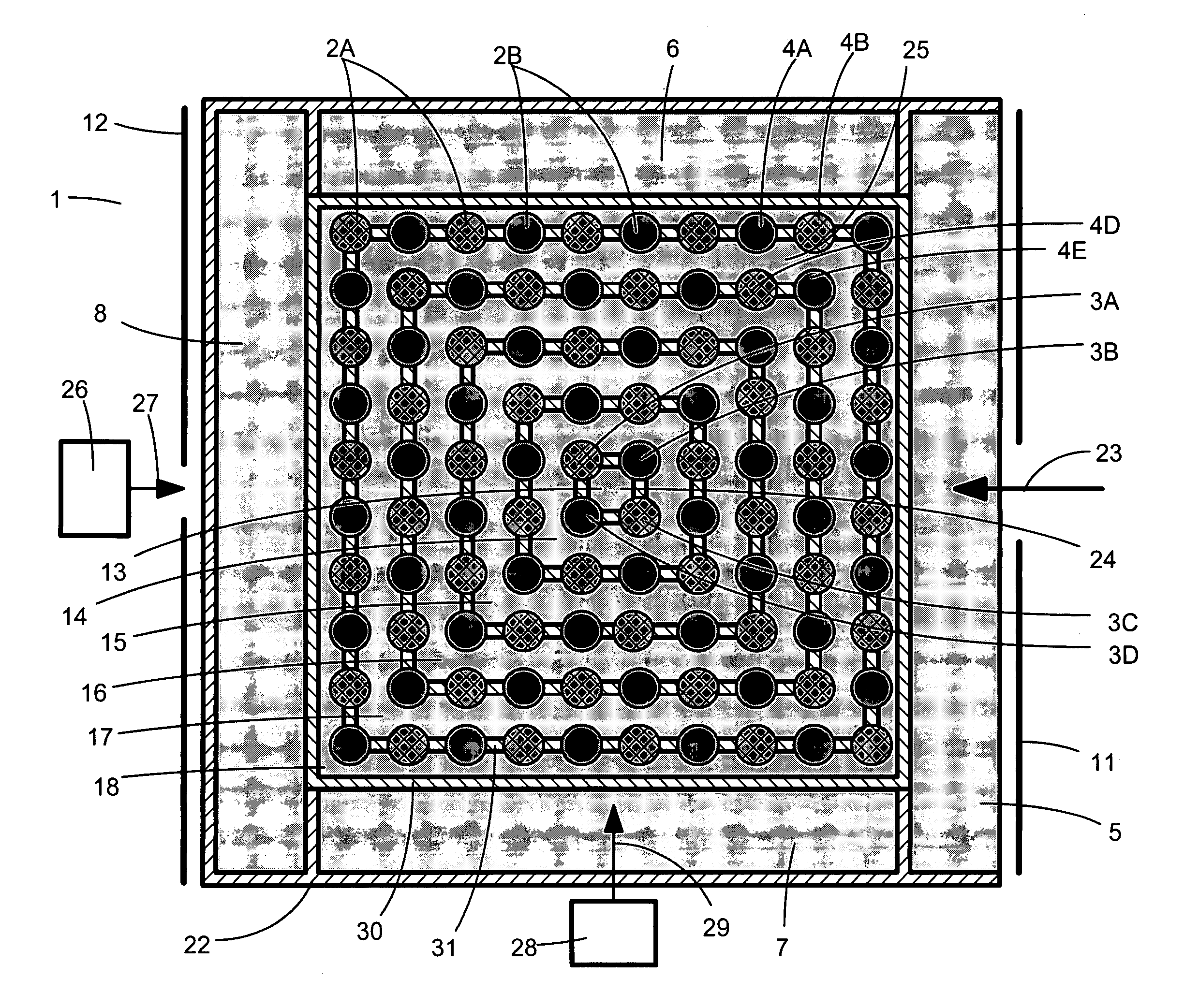
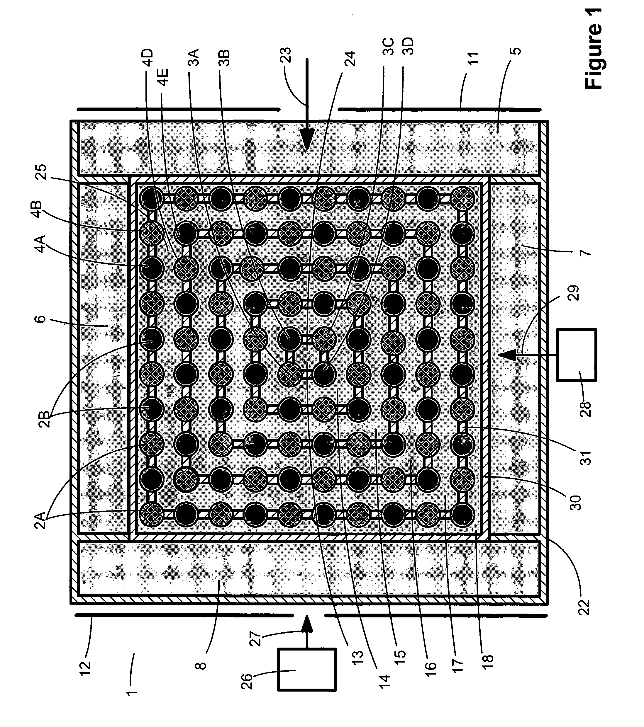
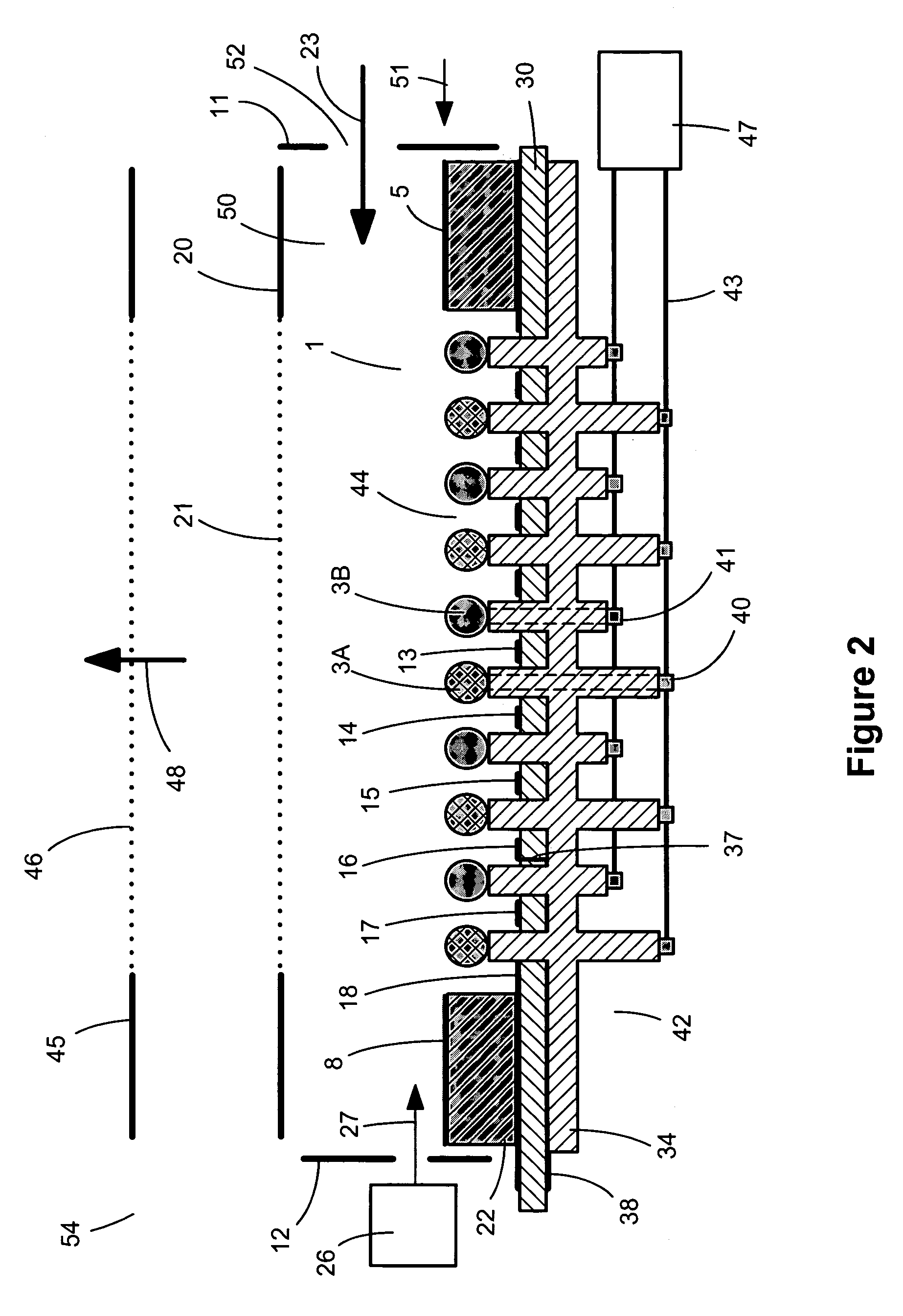
[0013]As described by Whitehouse et. al. in U.S. Pat. No. 6,683,301 B2, an electrostatic potential can be applied to a counter electrode positioned above or across from a surface of RF electrodes (RF surface). The counter electrode electrostatic potential can be set relative to the DC offset potential applied to the RF surface electrodes to move ions toward or away from the RF surface. Ions approaching the RF surface are prevented from hitting the RF electrode surfaces by the repelling “pseudo force field” formed by the RF voltage. A “pseudo potential well” is created capable of trapping ions of moderate translational energy over a wide range of mass-to-charge values between the counter electrode and the RF surface. Ions directed toward the RF surface by an increased electrical potential applied to a counter electrode tend to move back and forth in the pseudo energy well that forms in the center of RF electrode sets. To control the position of ions trapped in these pseudo energy wells and to facilitate movement of ions along an RF surface, an RF surface configured according to the present invention comprises electrodes positioned behind the RF surface electrodes and on the sides of the RF surface electrode array in addition to the counter electrode. DC voltages are applied to such back and side electrodes during operation. The RF surface, configured according to the invention, comprises multiple DC back and side electrodes positioned to control trapped ion positions above or below the RF surface plane or to move ions along the RF surface when appropriate DC voltages are applied. Repelling electrostatic potentials are applied to the back electrodes relative to the local RF offset potential to move ions trapped in local energy wells above the RF trapping surface. The distance that the repelling DC potentials applied to back electrodes penetrate between the RF electrodes is a function of the RF electrode tip shape and spacing geometry as well as the relative electrostatic potentials applied to the back electrodes, side electrodes, the RF electrode offset and the counter electrode. As the repelling potential from the back electrodes is increased the energy well depth between RF electrode sets decreases allowing ions to move more freely along the RF surface during operation. In some cases it is advantageous to preferably repel ions at some positions along the RF surface and attract them at others. For example, the back electrodes can be segmented to provide an attractive potential in a region in space where it is desirable to encourage ions to leak through the gaps in the electrodes, and to provide a retarding potential in regions of space to discourage ions from leaking through the gaps.
[0025]In another embodiment of the invention, the RF field-generating surface can be configured as at least one electrode assembly in an ICR cell. Ions entering the ICR cell can be captured and trapped along one or more RF field-generating surfaces and selectively directed into the center of the FTMS cell for FTMS analysis. Ions can be introduced into the ICR cell through an ion guide integrated into one RF surface assembly. In one embodiment of the invention, an ICR cell comprises two RF surface end electrode assemblies. Back electrode and RF electrode voltages are applied in the FTMS magnetic field such that ions rotate around the magnetic field axis in a sheet that is parallel to two RF surfaces. When operating this embodiment of the invention, rotating ions in the ICR cell experience minimum electric field gradients along the center axis of the FTMS cell, resulting in improved resolving power during mass to charge analysis.

Problems solved by technology

However, there is often a trade-off between sensitivity and resolving power, for example, when portions of the angular and / or spatial distributions of the sampled ion population must be sacrificed in order to achieve high resolving power.
Typically, a relatively small portion of the sample ion population from a continuous ion beam may be analyzed at a time, resulting in relatively low duty cycle efficiency.
However, the continuous transfer of externally-generated ions into such a three-dimensional RF-quadrupole ion trap is problematic because ions with energies low enough to be trapped will only be able to overcome the RF fields and enter the trap during a relatively short segment of the RF cycle time, resulting in a relatively low duty cycle.
Another disadvantage is that such an electrode geometry produces pulsed TOF acceleration fields that are generally not optimum for achieving maximum TOF mass resolving power.
Relatively poor performance resulted from difficulties in efficient trapping of ions due to the non-ideal trapping fields, as well as from scattering of ions by the sample gas and by the gas introduced to collisionally cool the ions in the trap, which degrades TOF mass resolution and sensitivity.
Disadvantages of this approach, as well as that of Enke, et al., include: 1) sample gas is introduced directly into the TOF optics, degrading the vacuum and causing ion scattering; 2) electron impact ionization results in substantial fragmentation which renders this ionization method impractical for mass analysis of many types of samples, such as large biomolecules; and 3) the sample needs to be introduced into the TOF as a gas, which makes this approach incompatible with non-volatile samples; and 4) the ionization efficiency is relatively small given the poor overlap between the neutral sample molecules and the electron beam.
However, the inventions disclosed by Whitehouse '301 and '941 require that the RF fields generated by an RF surface be sufficiently intense that ions are not able to come close enough to the RF surface to be trapped in the local potential wells between the RF electrodes.
While such configurations lead to improved TOF performance, nevertheless, the relatively poor localization of trapped ions parallel to the RF surface precludes additional possible improvements and functionalities.
For example, fragmentation of trapped ions by photon-induced dissociation via a focused, pulsed laser beam is relatively inefficient because the laser beam pulse is able to intersect only a small fraction of the trapped ion population with each pulse.
Further, any interaction between trapped ions and other reagent species, such as electron transfer dissociation (ETD) ions, is relatively inefficient without better spatial localization of the reactant species.
Even further, any opportunity to manipulate the spatial distribution of trapped ions is severaly limited, such as the ability to control the separation of the trapped ion population into sub-populations which are then directed to different TOF detectors, thereby providing better dynamic range, as described by Whitehouse, et al., in U.S. Application Publication No. 20020175292.
A major challenge with such interfaces is to direct as many of the ions produced at atmospheric pressure through one or more small orifices comprising the API interface.
The opposing requirements of high electric fields for ion focusing, and low electric fields for ion transport driven by gas dynamics, has resulted in inefficient transport of ions produced at or near atmospheric pressure into vacuum.
Another challenge has been to transport ions efficiently through multiple vacuum pumping stages.
Nevertheless, there remain compromises in these configurations between maximizing ion transport efficiency and minimizing gas flow between vacuum pumping stages.

Method used


Image

  • RF surfaces and RF ion guides
  • RF surfaces and RF ion guides
  • RF surfaces and RF ion guides

Examples


Embodiment Construction

[0064]A series of electrodes spaced in a grid pattern, to which RF of opposite phase and appropriate voltage is applied to adjacent RF electrodes, generates a field that reflects ions away from the surface. In the absence of a retarding field above the surface, ions of appropriate m / z and kinetic energy are reflected. As described by Whitehouse and Welkie in U.S. Pat. No. 6,683,301 B2, incorporated herein by reference, ions can be confined to a volume of space directly above the RF surface when an electrostatic retarding field is maintained above the surface, trapped by the RF pseudo potential wells. In one aspect of the present invention, the shape and size of the electrode tips, and the spacing between them, are adjusted such that an ion population is confined to localized volumes of space above gaps between the electrodes during ion trapping operation. Multiple Electrostatic electrodes configured behind and to the sides the RF surface, in the present invention, improve trapping e...


PUM


Abstract

Apparatus and methods are provided for trapping, manipulation and transferring ions along RF and DC potential surfaces and through RF ion guides. Potential wells are formed near RF-field generating surfaces due to the overlap of the radio-frequency (RF) fields and electrostatic fields created by static potentials applied to surrounding electrodes. Ions can be constrained and accumulated over time in such wells. During confinement, ions may be subjected to various processes, such as accumulation, fragmentation, collisional cooling, focusing, mass-to-charge filtering, spatial separation ion mobility and chemical interactions, leading to improved performance in subsequent processing and analysis steps, such as mass analysis. Alternatively, the motion of ions may be better manipulated during confinement to improve the efficiency of their transport to specific locations, such as an entrance aperture into vacuum from atmospheric pressure or into a subsequent vacuum stage.

Description

CROSS-REFERENCE TO RELATED APPLICATION[0001]This application claims priority to U.S. Provisional Application No. 60 / 573,667, filed on May 21, 2004, the disclosure of which is incorporated herein by reference in its entirety.FIELD OF THE INVENTION[0002]The present invention relates to mass spectrometry and in particular to apparatus and methods for temporary storage, manipulation and transport of ions using a combination of radio-frequency fields and electrostatic fields in mass spectrometric analysis.BACKGROUND OF THE INVENTION[0003]The application of mass spectrometry to the chemical analysis of sample substances has grown in recent years due in large part to advances in instrumentation and methods. Such advances include improved ionization sources, more efficient ion transport devices, more sophisticated ion processing, manipulation and separation methods, and mass-to-charge (m / z) analyzers with greater performance. However, while much progress has been made in these areas, there ...

Claims


Application Information

Patent Timeline
Patent Type & Authority Patents(United States)
IPC IPC(8): H01J49/42H01J49/04H01J49/10H01J49/16H01J49/40
CPCH01J49/062H01J49/42
Inventor WHITEHOUSE, CRAIG M.WELKIE, DAVID G.COUSINS, LISA
Owner PERKINELMER U S LLC
Learn More