Low noise, hybrid tuned wideband voltage controlled oscillator

a voltage control and wideband technology, applied in the direction of pulse automatic control, waveguide type devices, electronic characteristics varying frequency control, etc., can solve the problems of low phase noise, limiting the ability to detect weak signals, and the design of oscillators/vcos typically posing a challenge to the rf transceiver system, so as to improve the overall characteristics of the resonator, improve the reliability of the resonator, and improve the performance of the oscillator

Active Publication Date: 2008-04-29
SYNERGY MICROWAVE CORP
View PDF63 Cites 10 Cited by
  • Summary
  • Abstract
  • Description
  • Claims
  • Application Information

AI Technical Summary

Benefits of technology

[0025]In another aspect, the present invention comprises a hybrid tuning (coarse / fine) network for coarse-tuning and fine-tuning oscillator circuitry to avoid loading and degradation of the Q factor over the tuning range.
[0041]In accordance with yet another aspect of the present invention a hybrid tuned tunable ultra low phase noise oscillator is provided as is shown, for example, in FIG. 7. In accordance with this aspect of the present invention, the oscillator advantageously overcomes the aforementioned disadvantages of phase jitter and phase hits for applications where these parameters are important and is particularly usable at a frequency of 1200-3600 MHz. In addition, as the oscillator may be desirably configured in a standard housing, economies of scale may be achieved via the manufacturing process. As such, these oscillators may be desirably employed in mobile telephones, personal digital assistants, laptops or any other wireless device.

Problems solved by technology

Despite the continuous improvement in VCO technology, low phase noise typically remains a bottleneck and poses a challenge to RF transceiver (transmitter-receivers) design.
Furthermore, oscillator / VCO design typically poses a challenge to the RF trans-receiver system.
This is typically considered due to the more demanding parameters of the VCO design: low phase noise, low power consumption and wide frequency tuning range.
For example, in a receiver, the phase noise of the local oscillator limits the ability to detect a weak signal in the presence of a strong signal in an adjacent channel.
In a transmitter, phase noise results in energy being transmitted outside the desired channel or band.
MEMS (micro-electromechanical systems), SAW (surface acoustic wave) and ceramic-based resonators offer high Q factors but are relatively expensive and not easily amenable to the integrated circuit form.
Unfortunately, ceramic oscillators have disadvantages including a relatively limited operating temperature range, tuning range (which limits the amount of correction that can be made to compensate for the tolerance of other components in the oscillator circuitry) and an increased sensitivity to phase hits in the PLL.
In addition, oscillator circuitry becomes susceptible to phase-jitter and phase-hits due to noise-interference that is typically present on the tuning control voltage and resonator network.
A VCO that outputs a frequency that is less sensitive to tuning control voltage fluctuations imparts less phase jitter to the system, but suffers from a narrower tuning range, which limits its tuning band.
In applications where coarse-tuning and fine-tuning is required, phase noise performance typically suffers in the presence of a fine-tuning network that is incorporated with a coarse tuning network.
Further, the fine-tuning network typically adds extra noise and loading to the resonator circuit.
However, micro-stripline resonator-based oscillator circuitry typically exhibits a high degree of sensitivity to changes in the surrounding environment causing them to become microphonic and sensitive to noise interference.
In addition, micro-stripline or stripline resonators typically take up valuable space on the oscillator's circuit board.
Circuits of the type shown in FIG. 1B normally exhibit poor phase noise performance over the desired tuning range (e.g., 1200-3600 MHz).
In addition, the tuning range is limited because of the stability factor of the negative resistance-generating device, i.e., the transistor Q1, over the frequency band.

Method used


Image

  • Low noise, hybrid tuned wideband voltage controlled oscillator
  • Low noise, hybrid tuned wideband voltage controlled oscillator
  • Low noise, hybrid tuned wideband voltage controlled oscillator

Examples


Embodiment Construction

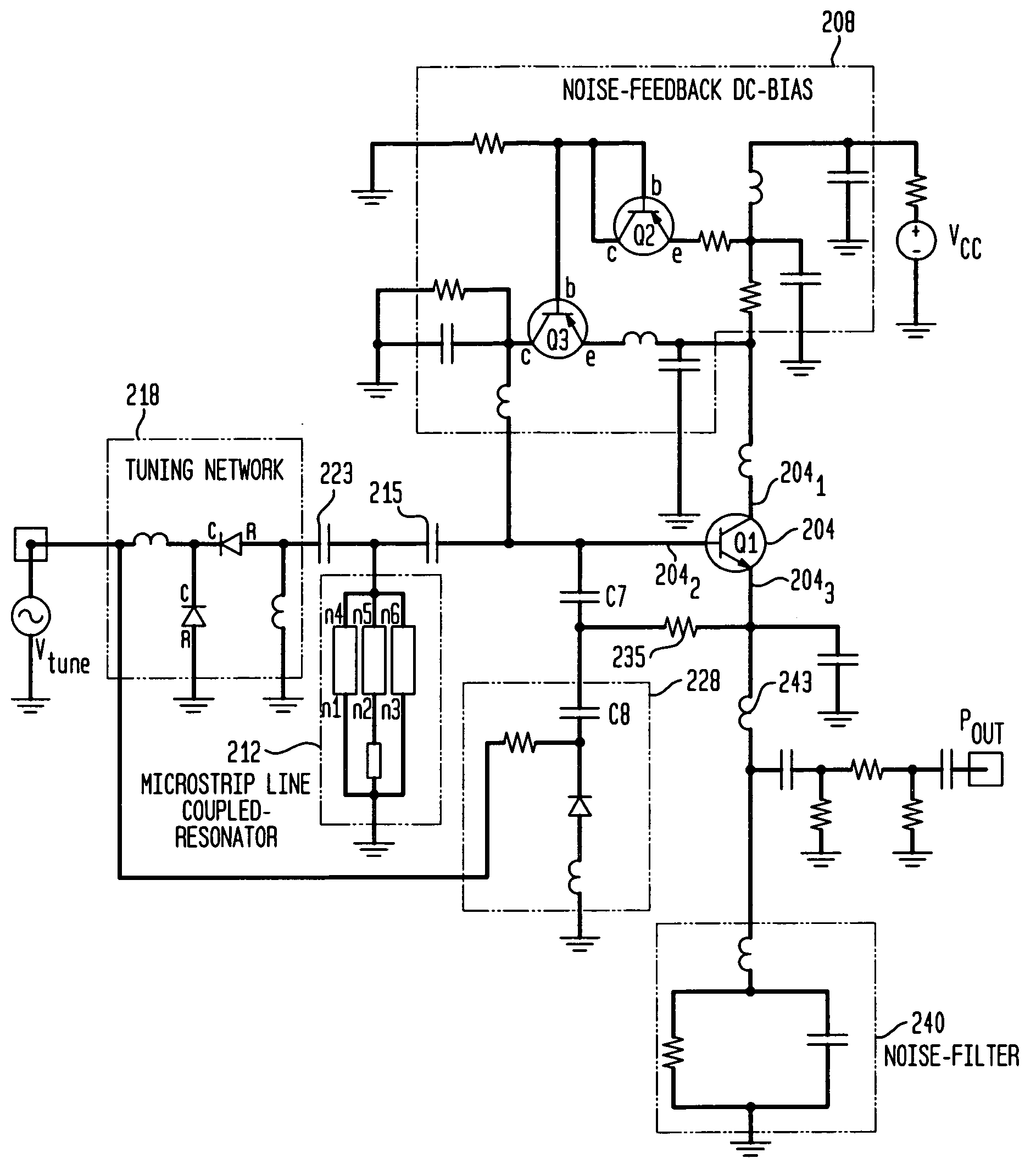
[0055]FIG. 2 is a schematic circuit diagram of voltage controlled oscillator 200 in accordance with an aspect of the present invention. The oscillator 200 includes an active device 204, which in the embodiment shown comprises a bipolar transistor Q1. In general, the active device 204 may comprise any three terminal device that can provide a 180 degree phase shift between the first terminal 2041 and second terminal 2042. The active device 204 may therefore also comprise a field effect transistor (FET). In the embodiment shown in FIG. 2, the first, second and third terminals 2041, 2042, 2043 of the active device 204 respectively comprise the collector, base and emitter of the transistor Q1.

[0056]The oscillator 200 also includes a noise feedback and DC bias network 208 coupled across the first and second terminals 2041, 2042. The network 208 includes a pair of transistors Q2 and Q3 that, in the arrangement shown, compensate for temperature fluctuations or fluctuations in the supply vol...


PUM


Abstract

An oscillator comprising an active device having first, second and third terminals, a plurality of micro-stripline resonators coupled together to form a coupled-resonator network, the coupled-resonator network being coupled to the second terminal of the active device and a tuning network coupled to the coupled-resonator network, the tuning network being operable to adjust the coupling between at least two of the resonators that form the coupled resonator network.

Description

CROSS-REFERENCE TO RELATED APPLICATIONS[0001]This application claims the benefit of the filing date of U.S. Provisional Patent Application No. 60 / 601,823 filed Aug. 16, 2004, the disclosure of which is hereby incorporated herein by reference.BACKGROUND OF THE INVENTION[0002]A voltage controlled oscillator (VCO) or oscillator is a component that can be used to translate DC voltage into a radio frequency (RF) voltage or signal. The magnitude of the output signal is dependent on the design of the VCO circuit and the frequency of operation is determined, in part, by a resonator that provides an input signal. In general, VCOs are designed to produce an oscillating signal at a particular frequency ‘f’ that corresponds to a given tuning voltage. In particular, the frequency of the oscillating signal is dependent upon the magnitude of a tuning voltage Vtune applied to a tuning diode network across a resonator circuit. The frequency ‘f’ may be varied from fmin to fmax and these limits are re...

Claims


Application Information

Patent Timeline
Patent Type & Authority Patents(United States)
IPC IPC(8): H01L23/66H03B5/18H03B9/14
CPCH03B1/04H03B5/1841H03B5/1847H03B5/1203H03B5/1231H03B5/1243H03B2200/0008H03B2200/0024H03B2200/0062H03B2200/0088H01L2924/0002H01L2924/00
Inventor ROHDE, ULRICH L.PODDAR, AJAY KUMARREBEL, REIMUNDPATEL, PARIMALSCHOEPF, KLAUS JUERGEN
Owner SYNERGY MICROWAVE CORP
Why Eureka
Try Eureka