
Heat exchange compressor

a compressor and heat exchange technology, applied in the direction of insulation, lighting and heating apparatus, borehole/well accessories, etc., can solve the problems of high installation, operation and maintenance costs, increased production costs, and increased production costs, so as to reduce the cost of compressing and reduce the cost of production. , the effect of simplifying the design

Inactive Publication Date: 2008-06-24
BI COMP
View PDF4 Cites 12 Cited by
  • Summary
  • Abstract
  • Description
  • Claims
  • Application Information

AI Technical Summary

Benefits of technology

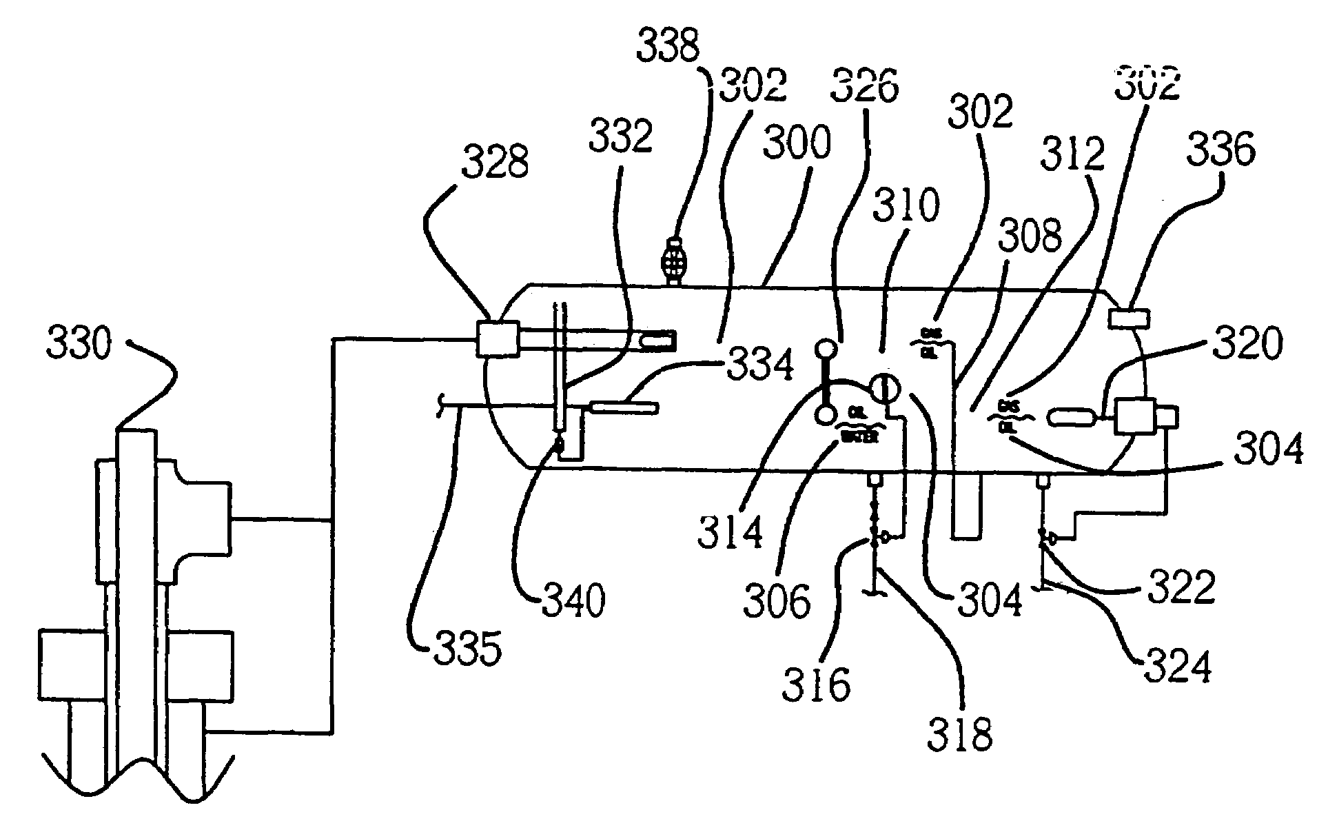
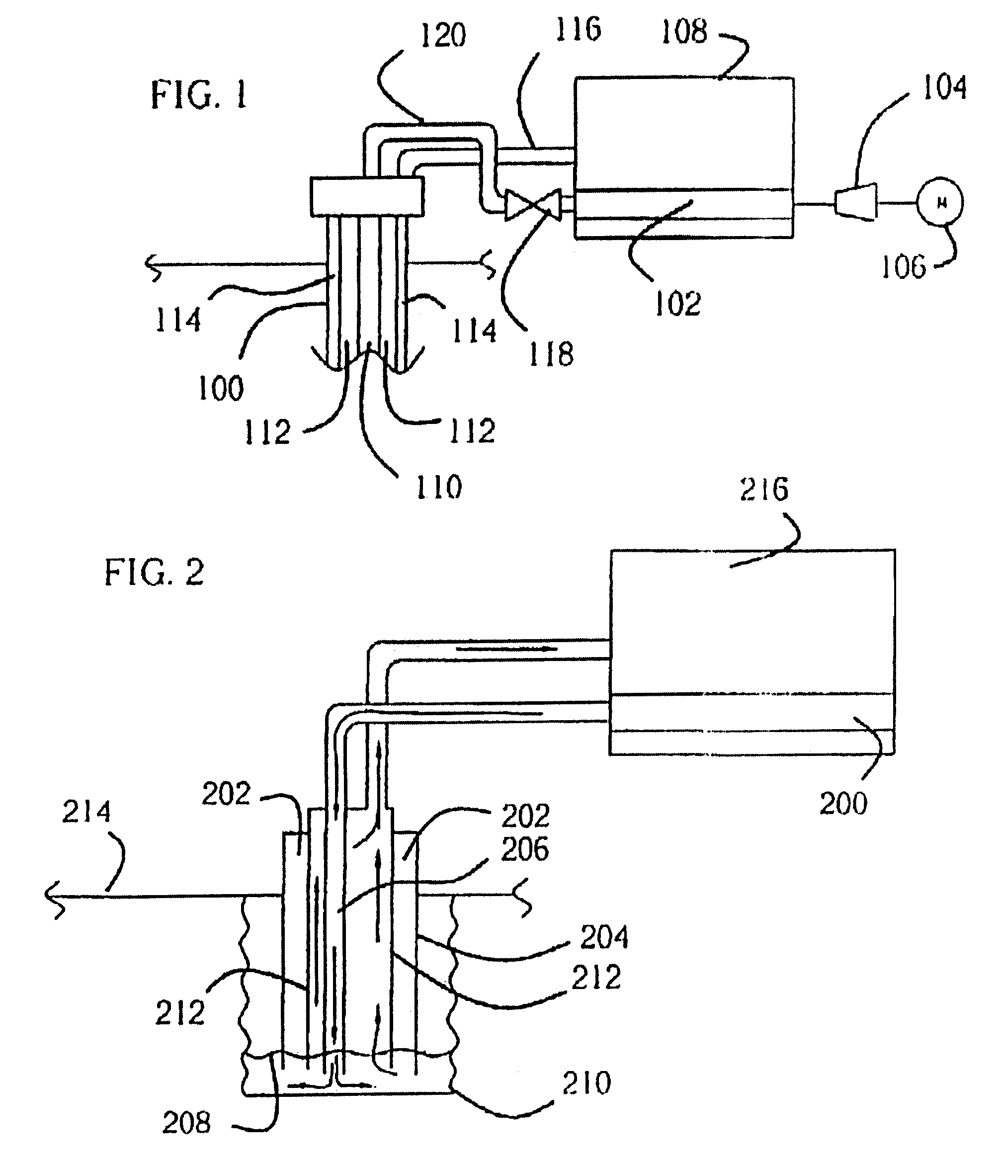
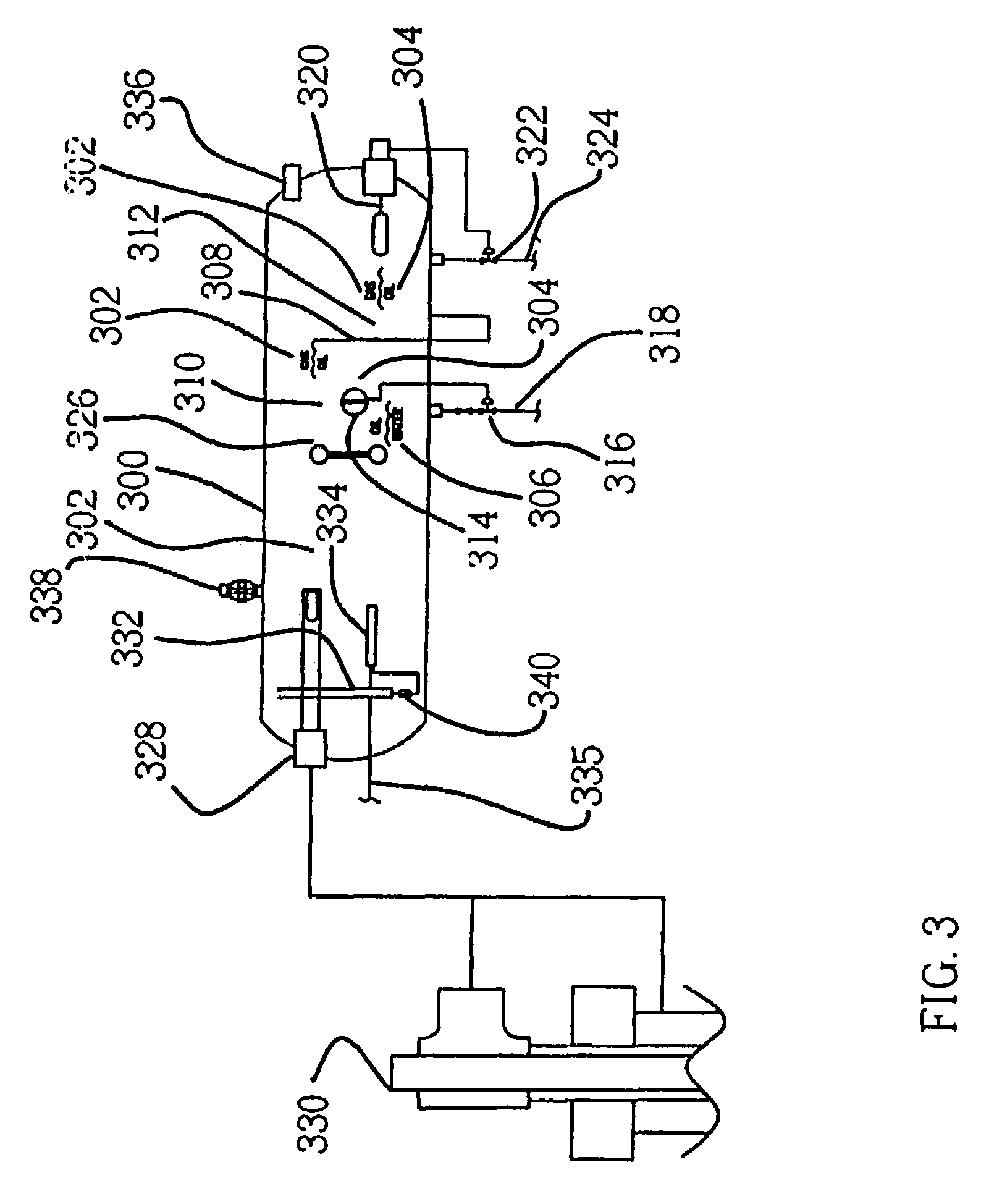
[0015]The HEC is also particularly attractive for cost-effective production because it greatly reduces the cost of compressing the lifting gas and separating the components produced by the well. This is achieved by simplifying the design and by utilizing energy from the other components of the system that would otherwise be lost by prior art compressors. Where the prior art uses gas compressors and pumps, the HEC pumps both gas and liquids simultaneously. Where prior art compressors require coolers and fans, the HEC dissipates the heat of compression by using it in separating the fluids from the subterranean formation for cooling. Where the prior art uses special control and accessories to control volume as well as pumping and compression speed, the HEC is controlled by the well head pressure. Where the prior art requires scrubbers to prevent fluids from entering the compression cylinders, the HEC function normally with fluids present. Where the prior art continues to use the same energy when production falls, the HEC automatically adjusts its stroke length and pumping rates to match the lower level of recovery.
[0016]Integrating HEC and BPU technology eliminates sealing packing, and therefore has substantially fewer moving parts than prior art technology. This reduces the danger of operating the recovery system and further reduces both initial costs as well as maintenance and operation costs. Another advantage of the HEC is that its power source and directional control can be remotely located, thereby reducing maintenance and downtime.
[0017]Another extremely attractive aspect of the HEC is that it can be safely installed at the wellhead. Shorter piping requirements, reduced pressure differentials, the lack of danger from burners, and the reduced danger from electrical sparks all contribute to the HEC's safety.

Problems solved by technology

However, even in wells with sufficient pressure initially, the pressure may decrease as the well gets older.
When the pressure diminishes to a point where the remaining oil is less valuable than the cost of bringing it to the surface using secondary recovery methods, production costs exceed profitability and the remaining oil is not brought to the surface.
The present invention utilizes gas lift technology, which is normally expensive to install, operate and maintain, and often dangerous to the environment.
Water wells employing free lift do not cool the compressed air used to lift the water to the surface.
The heat of compression in this gas is not utilized effectively and is rapidly dissipated when the lift gas is injected into a well.
Compressors for this service are expensive, dangerous, require numerous safety devices, and still may pollute the environment.
While both are suitable for compressing lifting gas, most prior art reciprocating compressors are costly to operate and maintain.
Moreover, existing reciprocating compressors are limited to compressing gases because they are not designed to pump both gas and liquids simultaneously and continuously.
While these serve the purpose intended, they are expensive and use power inefficiently compared to the present invention.
Another example of wasted energy and increased costs and maintenance is in the way the compressing cylinders are cooled in prior art compressors.
The fans and pumps in these cooling systems increase initial costs, and require energy, cleaning, and other maintenance.
Another example of the inefficiency of prior art technology relates to current means for separating recovery components.
In each case, controls, valves, burners and accessories add to the cost, environmental impact and maintenance of the equipment.
In remote field applications, this additional equipment can be both environmentally hazardous and financially expensive.

Method used


Image

  • Heat exchange compressor
  • Heat exchange compressor
  • Heat exchange compressor

Examples


example 1

[0072]The average well performs best with 40-60 PSIG back pressure on the lift system. The following example uses 40 PSI as the operating pressure in a BPU using a HEC with two cylinders with 108″ strokes and 1.1875″ ram cylinder bore radiuses and a 30 gallon per minute hydraulic pump. The low compression cylinder has a bore radius of 4″ and the high compression cylinder has a bore radius of 2″.[0073]Maximum Ram Pressure Available: 3000 PSIG[0074]Input Pressure to First Cylinder: 40 PSIG[0075]Swept Volume of First Cylinder: 5430 Cubic Inches[0076]Input Volume to First Cylinder: 11.7 Standard Cu.Ft. Gas[0077]Minimum Ram Pressure Required for First Cylinder: 2537 PSIG[0078]Discharge Pressure from First Cylinder: 210 PSIG[0079]Discharge Swept Volume from First Cylinder: 1357.7 Cubic Inches[0080]Minimum Ram Pressure Required for Second Cylinder: 2864 PSIG[0081]Input Volume to Second Cylinder: 2.85 Cubic Feet[0082]Discharge Pressure from Second Cylinder: 1000 PSIG[0083]Discharge Volume f...

example 2

[0085]The engine in Example 1 controls the pump frequency. Lifting capacity is controlled by the volume of the low pressure cylinder, the pressure ratio, and the number of strokes per time unit. For a gas from the separator at 40 PSIG, a pressure ratio of 4.1, and a frequency of 6 to 8 strokes per minute, the lifting capacity of the unit in Example 1 is 114,180 cubic feet per day. Based on ⅓ HP per gallon per 500 PSI, the power required to lift this volume is 56.57 horsepower (peek load at the end of the stroke) or 33.6 horsepower (average for entire stroke) for both cylinders at maximum operating pressures.

example 3

[0086]Over a two hour period during which oil and water are lifted from the well, 40,000 BTU is transferred from the compression cylinders of Example 1 to 4,000 pounds of water in a separator with a three stage capacity of 900 BBL / day, thereby increasing the water temperature 100 degrees F. This hot water is injected into the well for maintenance without interrupting production.


PUM


Abstract

An apparatus and process for simultaneously compressing liquids and gases and exchanging the heat of compression with fluids which may be the same liquids and gasses compressed. An apparatus and process for heating maintenance fluids using heat generated when the lift gas is compressed. The compressor may be used for recovering oil and gas from a subterranean formation wherein the production rate is controlled by the gas pressure at the well head, resulting in very slow strokes or pulses and bubbles of lift gas 500 feet long or longer. It may also be used for well maintenance using cooled injection gas from the well and heated fluids, which also may come from the well and be mixed with the well gas during compression, may be conducted without interrupting production.

Description

REFERENCE TO PRIOR APPLICATION[0001]This application is a divisional of U.S. Pat. No. 6,644,400, application Ser. No. 09 / 975,372, “Backwash Oil and Gas Production”, filed Oct. 11, 2001.FIELD OF THE INVENTION[0002]The present invention relates to a method of pumping crude oil, produce water, chemicals, and / or natural gas using an extremely efficient heat exchanging compressor with a novel internal integrated pump / injection system. The invention further relates to recovery systems that may be integrated in a single component. The invention further relates to oil and gas production systems with reduced environmental impact based on utilization of naturally occurring energy and other forces in the well and the process. The invention further relates to compressors controlled by naturally occurring gas from the well. The invention further relates to the prevention of decreased flow from a well due to corrosion, viscosity buildup, etc. downhole. The invention further relates to more cost-e...

Claims


Application Information

Patent Timeline
Patent Type & Authority Patents(United States)
IPC IPC(8): F28D7/02E21B43/12E21B43/34
CPCE21B43/122E21B43/34
Inventor IRWIN, JR., CHARLES CHESTER
Owner BI COMP
Learn More