
Broad-band-cholesteric liquid-crystal film, process for producing the same, circularly polarizing plate, linearly polarizing element, illiminator, and liquid-crystal display

a liquid crystal film, broad band technology, applied in the direction of polarising elements, lighting and heating apparatuses, instruments, etc., can solve the problems of difficult practical use, degraded display quality, and difficulty in covering all the visible light range, so as to reduce the number of manufacturing steps and the effect of reducing the number o

Inactive Publication Date: 2008-07-01
NITTO DENKO CORP
View PDF37 Cites 6 Cited by
  • Summary
  • Abstract
  • Description
  • Claims
  • Application Information

AI Technical Summary

Benefits of technology

The present invention provides a thin, broad band cholesteric liquid crystal film that has a wide reflection band and can be manufactured with a less number of manufacturing steps. The film can be used in a circularly polarizing plate, a linearly polarizer, a luminaire, and a liquid crystal display. The invention also provides a polarizing element system comprising a retardation layer and a reflection polarizer, which can be used in a wide viewing angle magnification liquid crystal display. The technical effects of the invention include a wide reflection band, a thin film, and a simplified manufacturing process.

Problems solved by technology

As the matters worse about the absorbed light, if a liquid crystal display is operated with an increased output of a light source beyond a level, it results in inconveniences that a polarizer is broken down by heat generation due to thermal conversion of absorbed light or that a display quality is degraded under thermal influence onto liquid crystal layer in a cell.
There has been, however, difficulty in covering all the range of visible light, since a selective reflection characteristic of a cholesteric liquid crystal is restricted to only a specific wavelength band.
With this value being larger, other functions as a liquid crystal (such as alignment characteristic, a liquid crystal temperature or the like) becomes insufficient, causing its practical use to be difficult.
This is because, as described in the publication of JP-A No. 6-281814, a quick change in pitch is difficult to be realized due to a theoretical issue in controlling a cholesteric pitch caused by a difference in ultraviolet exposure intensity in the thickness direction for a change in pitch length in the thickness direction and by a change in compositional ratio due to material transfer caused by a difference in polymerization speed accompanying the difference in ultraviolet intensity.
In a publication of JP-A No. 9-189811, at least three layers are necessary in order to cover all the range of visible light, and a long wavelength side is covered for betterment of a viewing angle characteristic, and the number of necessary laminated layers increases to as large as 4 to 5 in a case where a measure is taken against oblique incident light, which leads to more complexity in manufacture steps and increase in the number of steps, thereby unavoidably resulting in reduction in production yield.
As described above, in a conventional method in which multiple liquid crystal layers are laminated, however, (the publication of JP-A No. 9-189811), there has arisen a problem of increased number of steps due to lamination of multiple layers, while in a method as disclosed in the publication of JP-A No. 6-281814 or the specification of JP No. 3272668 in which a liquid crystal layer is thick, there has occurred a problem of cost-up.

Method used


Image

  • Broad-band-cholesteric liquid-crystal film, process for producing the same, circularly polarizing plate, linearly polarizing element, illiminator, and liquid-crystal display
  • Broad-band-cholesteric liquid-crystal film, process for producing the same, circularly polarizing plate, linearly polarizing element, illiminator, and liquid-crystal display
  • Broad-band-cholesteric liquid-crystal film, process for producing the same, circularly polarizing plate, linearly polarizing element, illiminator, and liquid-crystal display

Examples


example 1

[0135]Prepared was a methyl ethyl ketone solution (with a solid matter content of 30 wt %) of a mixture composed of 96 parts by weight of LC242 manufactured by BASF Corp. as a polymerizable mesogen compound (a), 4 parts by weight of LC756 manufactured by BASF Corp. as a polymerizable chiral agent (b) and 5 parts by weight of stilbene as a photoisomerizable material (c). The solution was cast on one stretched polyethylene terephthalate substrate and a solvent was removed off at 100° C. for 2 min for drying, followed by laminating the other polyethylene terephthalate substrate thereon. Then, the laminate was applied with ultraviolet illumination at 5 mW / cm2 for 3 min and further with heating at 100° C. for 10 sec, thereby obtaining a cholesteric liquid crystal film as a target.

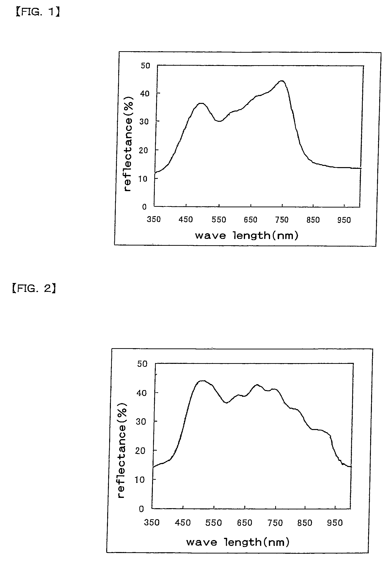
[0136]The one polyethylene terephthalate substrate was removed. A reflectance spectrum of a cholesteric liquid crystal film (a circularly polarizing plate) is shown in FIG. 1. The circularly polarizing plate had...

example 2

[0137]Prepared was a methyl ethyl ketone solution (with a solid matter content of 20 wt %) of a mixture composed of 96 parts by weight of the above described compound (1) as a polymerizable mesogen compound (a), 4 parts by weight of LC756 manufactured by BASF Corp. as a polymerizable chiral agent (b), 5 parts by weight of azobenzene as a photoisomerizable material (c) and 5 parts by weight of IRGACURE 369 (manufactured by Chiba Specialty Chemicals Corp.) as a photopolymerization initiator (d). The solution was cast on one stretched polyethylene terephthalate substrate and a solvent was removed off at 100° C. for 2 min for drying. Then, the laminate was applied with ultraviolet illumination at 20 mW / cm2 for 10 sec and further with heating, thereby obtaining a cholesteric liquid crystal film as a target.

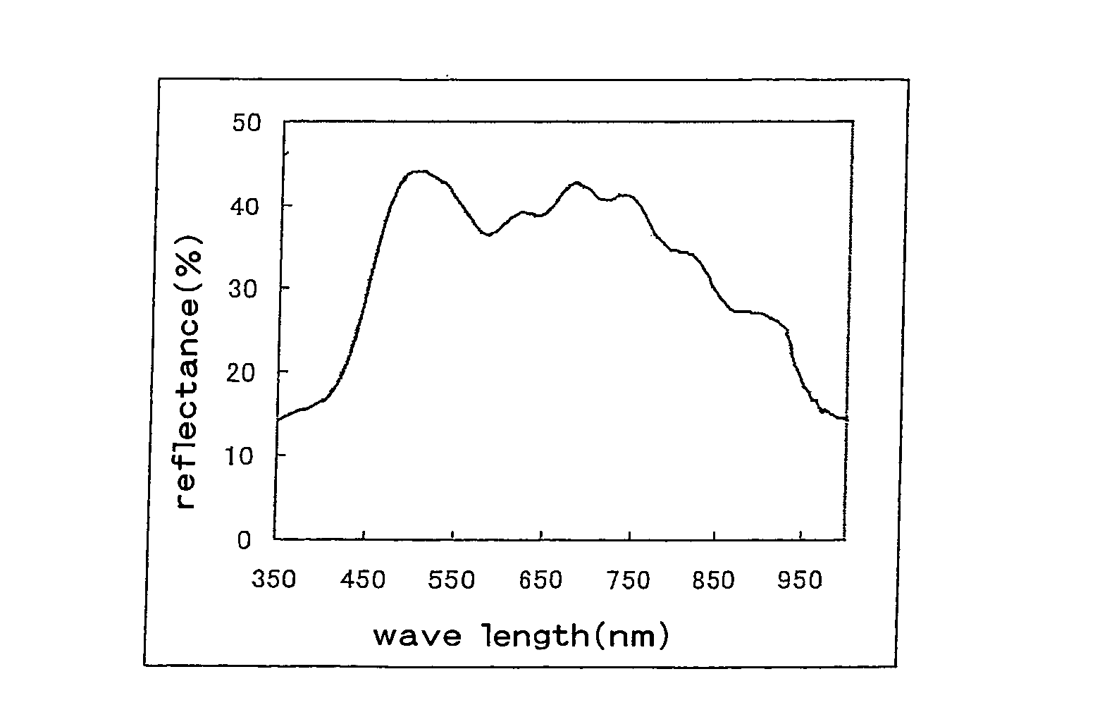
[0138]A reflectance spectrum of a cholesteric liquid crystal film (a circularly polarizing plate) is shown in FIG. 2. The obtained circularly polarizing plate had a good circularly pol...

example 3

[0139]The broad band cholesteric liquid crystal film (a circularly polarizing plate) obtained in Example 1 was adhered to a λ / 4 plate obtained by biaxially stretching a polycarbonate resin film (a thickness of 80 μm) in the direction along which a pitch length is narrower continuously toward the λ / 4 plate with an acrylic pressure sensitive adhesive with a thickness of 25 μm. Furthermore, an absorption type polarizing plate TEG1465DU manufactured by NITTO DENKO CO., LTD. was adhered thereto so that the transmission axis directions coincide with each other, to obtain a broad band polarizing plate.

[0140]The broad band polarizing plate was used as a lower plate for a TFT-LCD and placed on a side light type backlight, and a brightness enhancement percentage was measured with the result of a brightness enhancement 1.3 or more times as that in a case where a product of the present invention is not used. A brightness was measured with a viewing angle measuring instrument EZ-CONTRAST manufac...


PUM

PropertyMeasurementUnit
wavelengthaaaaaaaaaa
thicknessaaaaaaaaaa
speedaaaaaaaaaa

Abstract

A broad band cholesteric liquid crystal film of the present invention is a cholesteric liquid crystal film obtained by coating a liquid crystal mixture containing a polymerizable mesogen compound (a), a polymerizable chiral agent (b) and a photoisomerizable material (c) on a substrate to ultraviolet polymerize a coat of the liquid crystal mixture, and has a reflection bandwidth of 200 nm or more. A broad band cholesteric liquid crystal film of the present invention has a broad reflection band, is of a thin type and can be manufactured in less of manufacturing steps.

Description

TECHNICAL FIELD[0001]The present invention relates to a broad band cholesteric liquid crystal film and a manufacturing method therefor. A broad band cholesteric liquid crystal film of the present invention is useful as a circularly polarizing plate (a reflection polarizer). The present invention relates to a linearly polarizer, a luminaire and a liquid crystal display using the circularly polarizing plate. Moreover, the present invention relates to a polarizing element system using the circularly polarizing plate and a wide viewing angle magnification liquid crystal display using the polarizing element system.BACKGROUND ART[0002]Generally, a liquid crystal display has a structure in which a space between glass plates forming transparent electrodes is filled with a liquid crystal and polarizers are arranged before and after the glass plates. A polarizer used in such a liquid crystal display is manufactured in a procedure in which iodine or a dichloic dye is subjected to be adsorbed t...

Claims


Application Information

Patent Timeline
Patent Type & Authority Patents(United States)
IPC IPC(8): C09K19/52F21V7/22F21V9/14G02F1/13363G02B5/30
CPCG02B5/3016Y10T428/1036C09K2323/03G02B5/30G02F1/1335
Inventor TAKEDA, KENTAROUHARA, KAZUTAKATAKAHASHI, NAOKIFUKUOKA, TAKAHIRO
Owner NITTO DENKO CORP
Learn More