Imaging members

a technology of electrophotographic imaging and imaging members, applied in the field of electrophotographic imaging members, can solve the problems of surface cracking, charge transport layer, affecting copy quality, etc., and achieve the effect of increasing wear resistance and prolonging the functional life of the electrophotographic imaging member

Inactive Publication Date: 2008-08-19
XEROX CORP
View PDF17 Cites 46 Cited by
  • Summary
  • Abstract
  • Description
  • Claims
  • Application Information

AI Technical Summary

Benefits of technology

[0022]There are disclosed in various embodiments herein, processes and compositions for extending the functional life of an electrophotographic imaging member. These processes and compositions relate generally to a mechanically robust charge transport layer which has increased wear resistance to increase imaging member service life under normal functioning conditions in the field.

Problems solved by technology

Surface cracking has also been found to be caused by exposure to airborne chemical contaminants as the photoreceptor segments statically “park” or directly bend over the rollers after periods of photoreceptor belt non-use during machine idling.
Photoreceptor surface cracking is a critical mechanical issue seen in imaging members, particularly in flexible belts, because the cracks manifest themselves into printout defects that seriously impact copy quality.
Consequently, the charge transport layer is also susceptible to surface scratching, abrasion, wear, and filming which produce copy print-out defect problems as well.
However, not all of the solvent may be removed from the coating layer during drying.
The outgassing of the trapped solvent from the charge transport layer during storage and over the life of the photoreceptor causes dimensional contraction of the charge transport layer, causing increased internal strain in the charge transport layer.
Thus, in addition to the bending strain induced during dynamic photoreceptor belt flexing over each belt module support roller in a machine, this increase in internal strain will exacerbate charge transport layer cracking under normal belt functioning conditions in the field.
Since the contraction in belt direction is prevented by the applied tension as the belt is mounted over and around a belt support module, edge curling in the photoreceptor belt is an important issue.
Edge curling changes the distance between the belt surface and the charging device, causing non-uniform surface charging density which is visible as a “smile print” defect.
Since the charge transport layer of a typical negatively charged multilayered photoreceptor flexible belt is typically the outermost exposed layer, it is inevitably subjected to constant mechanical interactions against various electrophotographic imaging machine subsystems under a normal service environment.
As a result, the charge transport layer may frequently exhibit mechanical failures such as frictional abrasion, wear, and surface cracking due to fatigue dynamic belt flexing.
Under normal functioning conditions, exposure to the ozone species generated from the wires of a charging device is known to cause polymer binder chain scission, exacerbating charge transport layer cracking and wear problems.
Charge transport layer wear is also an issue because wear reduces thickness and thereby alters the equilibrium of the balancing forces between the charge transport layer and the anti-curl back coating, impacting imaging member flatness.
As a consequence, charge transport layer wear is a serious problem which significantly reduces the functional life of the imaging member.
However, while many of the abovementioned references attempt to offer solutions to the problems noted, they frequently create new ones.

Method used


Image

  • Imaging members
  • Imaging members
  • Imaging members

Examples


control example 1

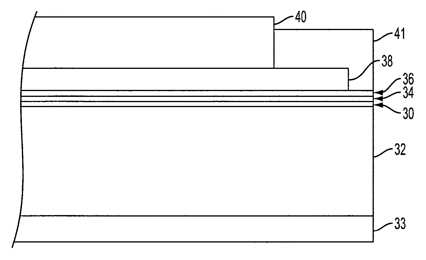
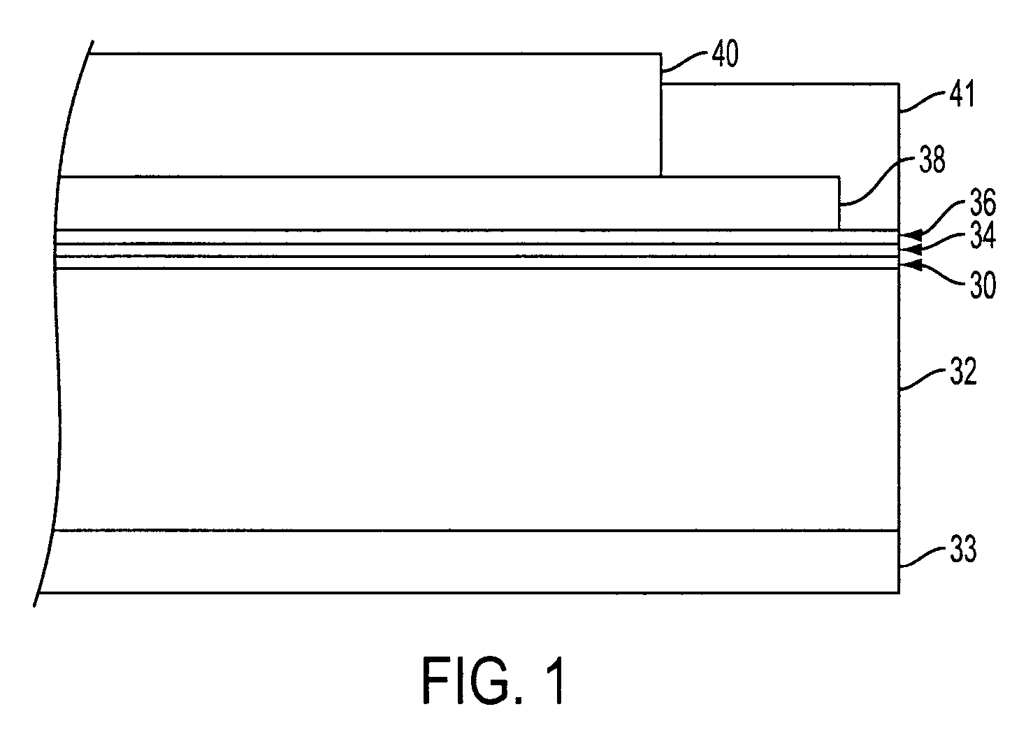
[0090]A flexible electrophotographic imaging member web was prepared by providing a 0.02 micrometer thick titanium layer coated on a substrate of a biaxially oriented polyethylene naphthalate substrate (KADALEX, available from DuPont Teijin Films.) having a thickness of 3.5 mils (89 micrometers). The titanized KADALEX substrate was extrusion coated with a blocking layer solution containing a mixture of 6.5 grams of gamma aminopropyltriethoxy silane, 39.4 grams of distilled water, 2.08 grams of acetic acid, 752.2 grams of 200 proof denatured alcohol and 200 grams of heptane. This wet coating layer was then allowed to dry for 5 minutes at 135° C. in a forced air oven to remove the solvents from the coating and effect the formation of a crosslinked silane blocking layer. The resulting blocking layer had an average dry thickness of 0.04 micrometer as measured with an ellipsometer.

[0091]An adhesive interface layer was then applied by extrusion coating to the blocking layer with a coating...

control example 2

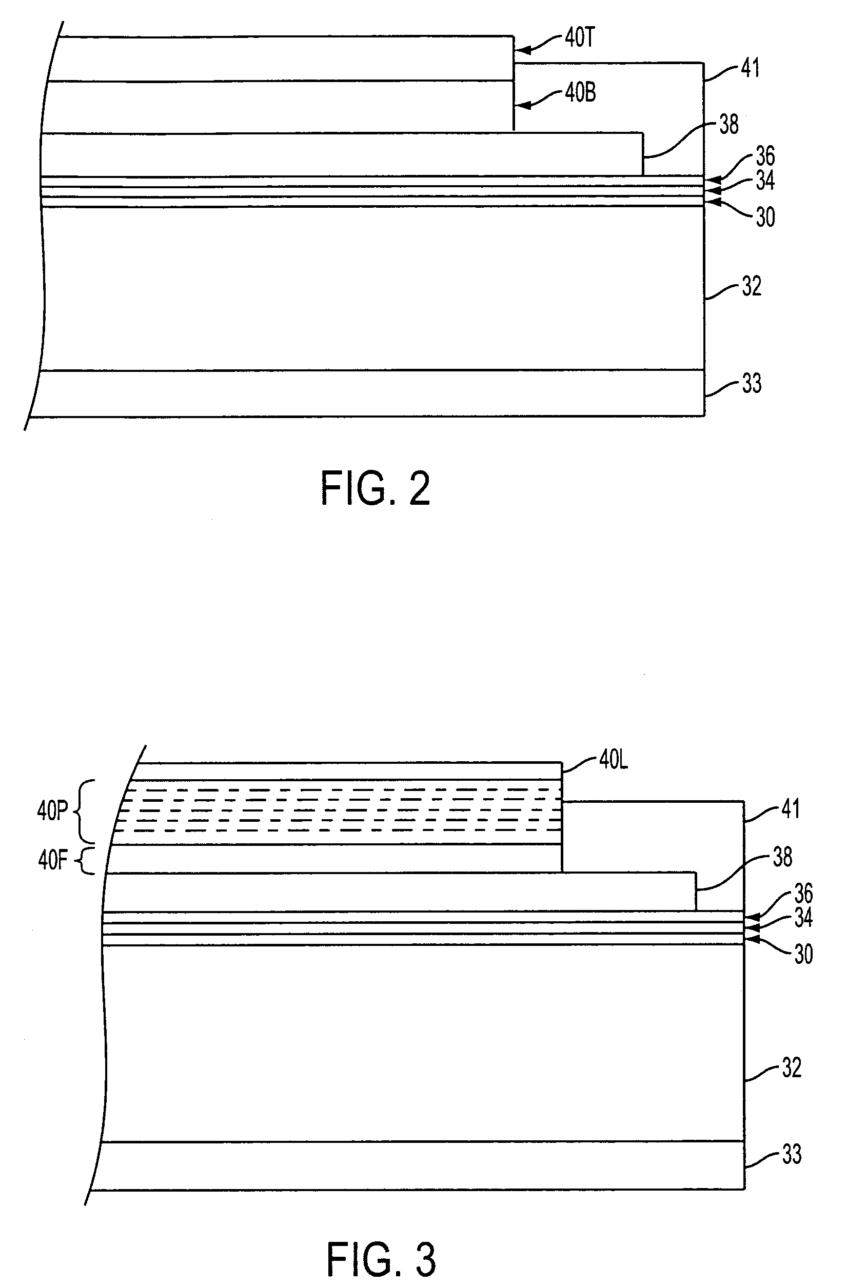
[0098]A flexible electrophotographic imaging member web was prepared in the same manner and using the same materials as those described in Control Example 1, except that the 29 micrometers thick charge transport layer was prepared to include a 5 wt-% nanoparticle PTFE (MP1100, available from DuPont) dispersion.

example 1

Disclosure Example 1

[0099]Two flexible electrophotographic imaging member webs were fabricated using the same materials and the same process as that described in Control Example 2, except that the charge transport layer coating solutions were prepared to include a Bisphenol A bisallyl carbonate monomer (HIRI®; commercially available from PPG, Inc.), an organic high boiler liquid. The two coating solutions were then each applied onto the charge generating layer of an imaging memberweb and followed by subsequent drying at elevated temperature to give two imaging member web stocks having 2 wt-% HIRI® and 8 wt-% HIRI®, respectively, based on the resulting dried weight of each charge transport layer. The charge transport layer of each web was 29 micrometers in thickness.


PUM

PropertyMeasurementUnit
sizeaaaaaaaaaa
particle sizeaaaaaaaaaa
sizeaaaaaaaaaa

Abstract

An electrophotographic imaging member having a thermoplastic charge transport layer comprising a charge transport compound, a polycarbonate polymer binder, a particulate dispersion, and a high boiler compatible organic liquid. The disclosed charge transport layer exhibits enhanced wear resistance, excellent photoelectrical properties, and good print quality.

Description

BACKGROUND[0001]This disclosure relates, in various embodiments, to electrostatographic imaging members. More particularly, the disclosure relates to an improved outermost exposed imaging layer, such as a charge transport layer, of an electrostatographic imaging member which extends the mechanical service life of the member.[0002]Electrostatographic imaging members are known in the art. Typical electrostatographic imaging members include photoreceptors for electrophotographic imaging systems and electroreceptors such as ionographic imaging members for electrographic imaging systems. Generally, these imaging members comprise at least a supporting substrate and at least one imaging layer comprising a thermoplastic polymeric matrix material. In a photoreceptor, the photoconductive imaging layer may comprise only a single photoconductive layer or a plurality of layers such as a combination of a charge generating layer and one or more charge transport layer(s).[0003]Electrostatographic i...

Claims


Application Information

Patent Timeline
Patent Type & Authority Patents(United States)
IPC IPC(8): G03G15/02
CPCG03G5/051G03G5/0517G03G5/0614G03G5/0539G03G5/0609G03G5/0535G03G5/061443
Inventor LIN, LIANG-BIHYU, ROBERT C. U.LOPEZ, FRANCISCOWU, JINCHAMBERS, JOHN S.
Owner XEROX CORP
Why Eureka
Try Eureka