High strength diffusion brazing utilizing nano-powders

a nano-powder and diffusion brazing technology, applied in the field of metalurgical field, can solve the problems of component damage, component damage, and various types of damage and deterioration of components, and achieve the effects of reducing the cost of components

Inactive Publication Date: 2008-08-26
SIEMENS ENERGY INC
View PDF33 Cites 25 Cited by
  • Summary
  • Abstract
  • Description
  • Claims
  • Application Information

AI Technical Summary

Problems solved by technology

During the operation of these components in the harsh operating environment of a gas turbine, various types of damage and deterioration of the components may occur.
For example, the surface of a component may become cracked due to thermal cycling or thermo-mechanical fatigue or it may be eroded as a result of impacts with foreign objects and corrosive fluids.
Furthermore, such components may be damaged during manufacturing operations even prior to entering service.
Fusion welding of superalloy materials is known to be a difficult process to control due to the tendency of these materials to crack at the area of the weld deposit / joint.
One limitation of brazing is that brazed joints are typically much weaker than the base alloy, and so they may not be appropriate in all situations, such as repairs on the most highly stressed areas of the component.
Upon completion of this cycle, typical braze alloys will have formed undesirable large blocky or script-like brittle phases composed of chromium, titanium, and the family of refractory elements (e.g., tungsten, tantalum) combined with the melting point depressants.
These brittle phases weaken the repaired component and decrease its ductility in the region of the repair.
Such a liquid phase diffusion bonding process is capable of forming a joint with material properties approximating but typically not as good as those of the base alloy.

Method used


Image

  • High strength diffusion brazing utilizing nano-powders
  • High strength diffusion brazing utilizing nano-powders

Examples


Embodiment Construction

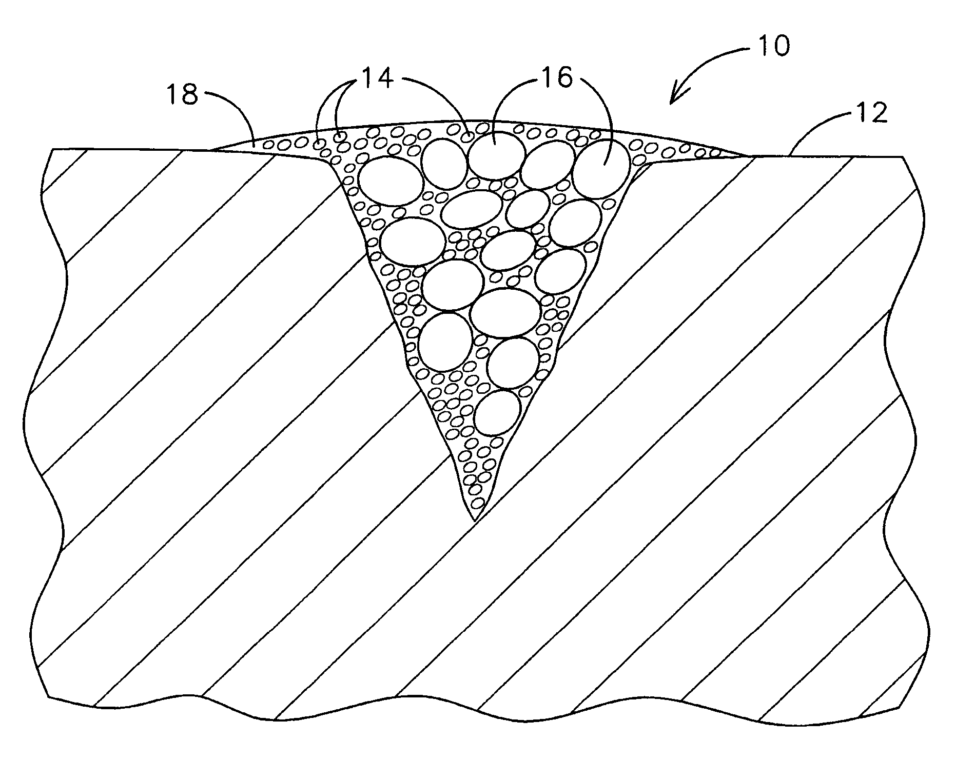
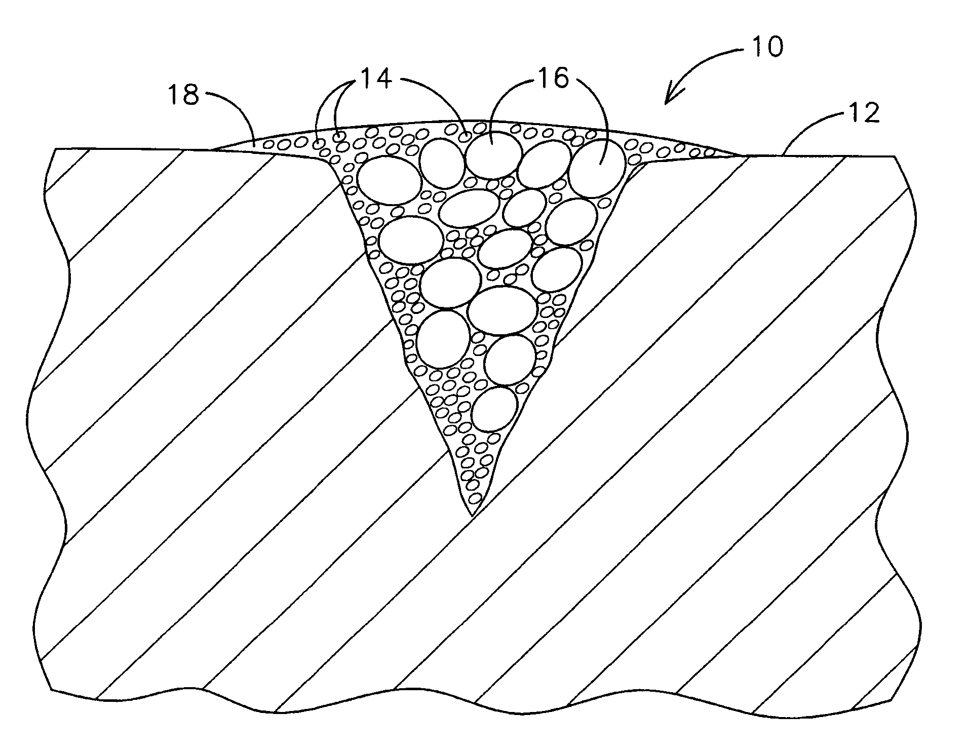
[0008]The sole FIGURE illustrates an improved brazing material 10 filling a surface-opening crack in a superalloy component 12. The brazing material (mixture) 10 includes filler particles of a base alloy 14 such as a superalloy with a composition similar to that of the component 12, and optionally particles of a braze alloy (braze filler) 16, suspended in a carrier 18. The materials selected for the component 12, base alloy (superalloy filler) 14, braze alloy (braze filler) 16 and carrier 18 may have chemical compositions known in the art of brazing or other compositions particularly suited for a specific application. However, the size of the particles of base alloy 14 is less than the size of such particles used in prior art brazing materials. In particular, the size of particles of base alloy 14 are selected to be small enough so that the melting temperature of the base alloy particles 14 is significantly less than the melting temperature that the same material would exhibit in pa...


PUM

PropertyMeasurementUnit
sizeaaaaaaaaaa
sizeaaaaaaaaaa
sizeaaaaaaaaaa

Abstract

A braze material (10) including nano-sized filler material particles (14). The nano-sized particles will melt at a temperature significantly lower than the micron-sized particles used in prior art braze materials, thereby eliminating or reducing the need for the addition of temperature depressant materials such as boron or silicon. The resulting braze joint is substantially free of detrimental boride and suicides phases, thereby improving the material properties of the joint, eliminating the need for a separate post-braze diffusion heat treatment, and permitting a subsequent welding operation with reduced risk of cracking. The braze heat treatment may also function as a solution heat treatment, a pre-weld heat treatment or a post-weld heat treatment.

Description

RELATED APPLICATIONS[0001]This application is a continuation-in-part and claims benefit of the Jan. 24, 2002, filing date of U.S. application Ser. No. 10 / 056,141 now U.S. Pat. No. 6,726,086 which is incorporated herein by reference.FIELD OF THE INVENTION[0002]This application applies generally to the field of metallurgy, and more specifically to the manufacturing and repair of alloy articles, and in particular, to the manufacturing and repair of a superalloy component of a gas turbine engine.BACKGROUND OF THE INVENTION[0003]High temperature cobalt-based and nickel-based superalloys are commonly used in the manufacture of gas turbine engine components, including combustors, rotating blades and stationary vanes. During the operation of these components in the harsh operating environment of a gas turbine, various types of damage and deterioration of the components may occur. For example, the surface of a component may become cracked due to thermal cycling or thermo-mechanical fatigue o...

Claims


Application Information

Patent Timeline
Patent Type & Authority Patents(United States)
IPC IPC(8): B23K31/02B23K35/34B23K20/02B23K35/02B23K35/30C21D9/50C22F1/10
CPCB23K20/023B23K35/0244B23K35/304C22F1/10B23P6/002B23P6/007B23K35/025C21D9/50B23K2201/001B23K2101/001
Inventor PHILIP, VINOD
Owner SIEMENS ENERGY INC
Why Eureka
Try Eureka