
Patterning process and undercoat-forming material

a technology of undercoat and patterning process, applied in the field of patterning process and undercoat-forming material, can solve the problems of affecting the etching resistance of the substrate, the approach of thickening the anti-reflective film encountering a limit, and the essential limit of resolution determined by the light source wavelength, so as to achieve the effect of improving the etching resistance and high transparency

Active Publication Date: 2008-09-23
SHIN ETSU CHEM CO LTD
View PDF37 Cites 12 Cited by
  • Summary
  • Abstract
  • Description
  • Claims
  • Application Information

AI Technical Summary

Benefits of technology

The copolycondensate material effectively suppresses substrate reflection and demonstrates high resistance to etching, maintaining pattern integrity and reducing etching-induced surface roughness, thus addressing the limitations of existing materials.

Problems solved by technology

While a number of recent efforts are being made to achieve a finer pattern rule in the drive for higher integration and operating speeds in LSI devices, the commonly used light exposure lithography is approaching the essential limit of resolution determined by the light source wavelength.
As the molecular weight of a base resin increases, there arise problems that more pinholes generate after spin coating, filtration becomes difficult, a viscosity change with the passage of time leads to a variation of film thickness, and crystals precipitate at the nozzle tip.
However, when the etching load that the overlying resist layer has to bear is considered, the approach of thickening the antireflective film encounters a limit, the limit of film thickening being of the order of the second base of up to 100 nm.
This has the advantages that it can be formed by CVD of a gas mixture of silane and ammonia, and the etching load on resist is light due to a high selective ratio of etching relative to resist, but the range of application is restricted because of difficulty of peeling.
Because of a nitrogen atom-containing basic film, another drawback arises that it is susceptible to footing in the case of positive resist and an undercut profile in the case of negative resist.
However, since most light-absorbing agents have aromatic groups or double bonds, the addition of a light-absorbing agent undesirably increases dry etching resistance and rather reduces a selective ratio of dry etching relative to the resist.
In the ArF exposure lithography of the next generation, acrylic or alicyclic polymers are used as the resist material, indicating that the etching resistance of the resist becomes poor.
A further consideration is the problem that the thickness of antireflective film must be increased as mentioned above.
Then, etching is an acute problem.
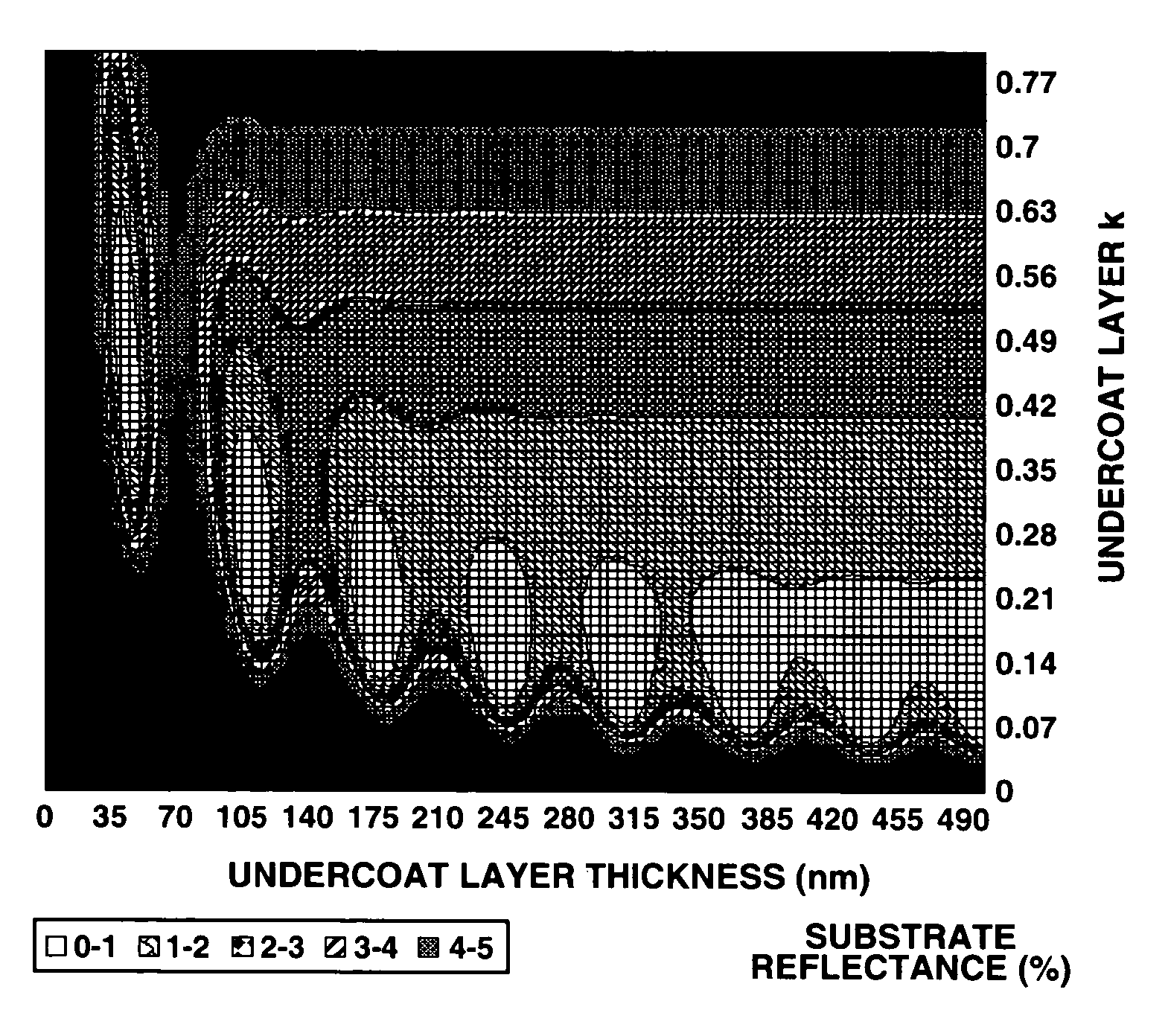
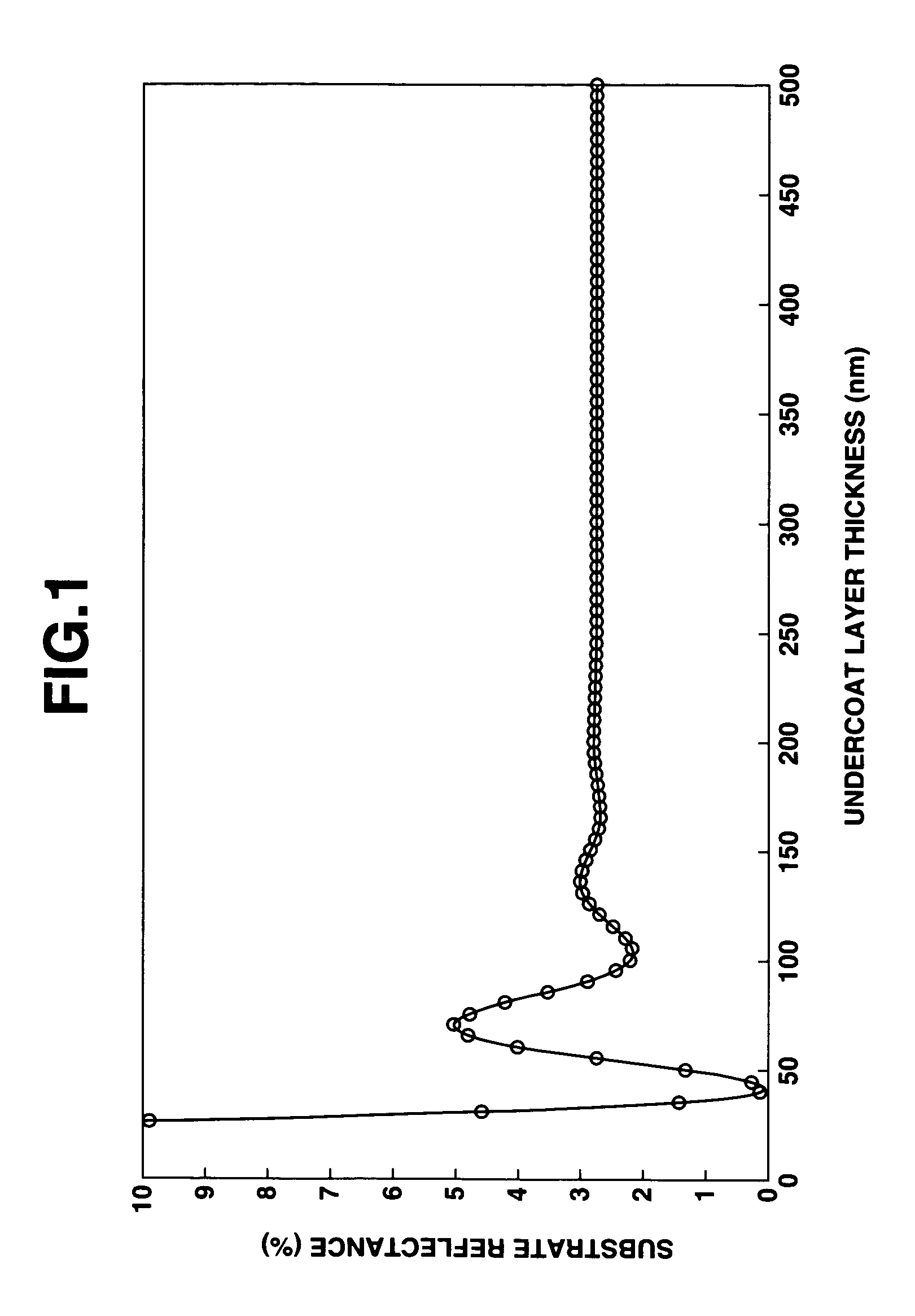
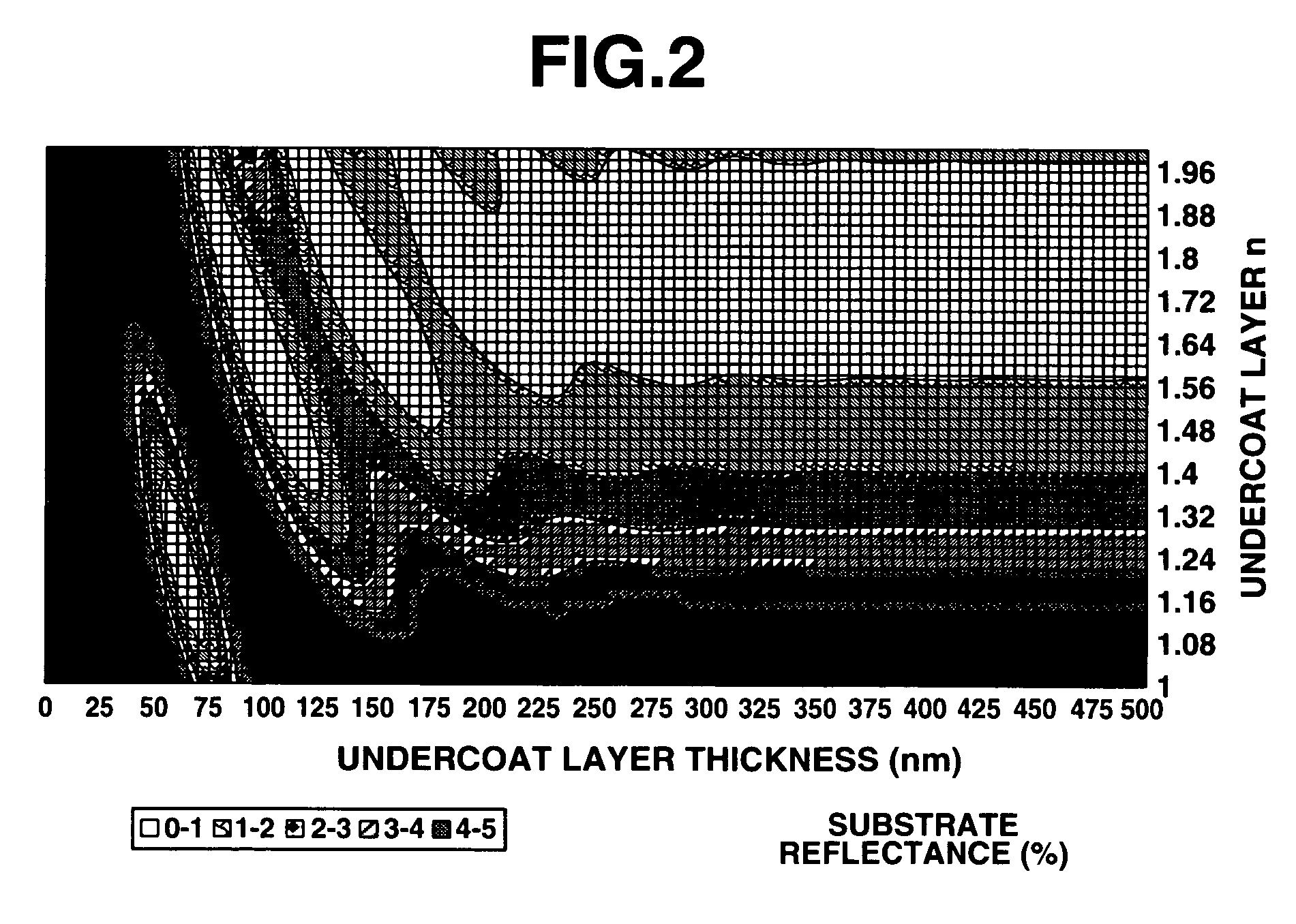
At a film thickness of at least 300 nm, the variation of reflectivity due to a film thickness change is substantially converged so that the antireflection effect due to phase difference control is no longer expected.
However, the resistance of an acrylic compound to substrate etching is weak as compared with polyhydroxystyrene, and a considerable proportion of the acrylic compound must be copolymerized in order to reduce the k value.

Method used


Image

  • Patterning process and undercoat-forming material
  • Patterning process and undercoat-forming material
  • Patterning process and undercoat-forming material

Examples


synthesis example 1

[0220]A 300-ml flask was charged with 144 g (1 mol) of 1-naphthol and 0.01 g of trifluoromethanesulfonic acid. With stirring at 50° C., 132 g (1 mol) of dicyclopentadiene was added dropwise over one hour. The solution was stirred at the temperature for one hour, heated to 150° C. and stirred for 2 hours, completing reaction. The unreacted reactants were removed by vacuum distillation. The reaction product was dissolved in 200 g of 1,2-dichloroethane, which was washed with water to remove the catalyst and metal impurities. On vacuum removal of 1,2-dichloroethane, 230 g of Polymer 1 was recovered.

[0221]The molecular weight (Mw) and dispersity (Mw / Mn) of Polymer 1 were determined by GPC using polystyrene standards. From 1H-NMR analysis, the ratio of naphthol to dicyclopentadiene in the polymer was determined.[0222]Polymer 1: 1-naphthol / dicyclopentadiene molar ratio=0.55:0.45[0223]Mw=4,400[0224]Mw / Mn=3.1

synthesis example 2

[0225]A 300-ml flask was charged with 144 g (1 mol) of 1-naphthol and 0.007 g of trifluoromethanesulfonic acid. With stirring at 50° C., 66 g (0.5 mol) of dicyclopentadiene was added dropwise over one hour. The solution was stirred at the temperature for one hour, heated to 150° C. and stirred for 2 hours, completing reaction. The unreacted reactants were removed by vacuum distillation. The reaction product was dissolved in 200 g of 1,2-dichloroethane, which was washed with water to remove the catalyst and metal impurities. On vacuum removal of 1,2-dichloroethane, 180 g of Polymer 2 was recovered.

[0226]The molecular weight (Mw) and dispersity (Mw / Mn) of Polymer 2 were determined by GPC using polystyrene standards. From 1H-NMR analysis, the ratio of naphthol to dicyclopentadiene in the polymer was determined.[0227]Polymer 2: 1-naphthol / dicyclopentadiene molar ratio=0.77:0.23[0228]Mw=5,200[0229]Mw / Mn=2.8

synthesis example 3

[0230]A 300-ml flask was charged with 174 g (1 mol) of 7-methoxy-1-naphthol and 0.007 g of trifluoromethanesulfonic acid. With stirring at 50° C., 66 g (0.5 mol) of dicyclopentadiene was added dropwise over one hour. The solution was stirred at the temperature for one hour, heated to 150° C. and stirred for 2 hours, completing reaction. The unreacted reactants were removed by vacuum distillation. The reaction product was dissolved in 200 g of 1,2-dichloroethane, which was washed with water to remove the catalyst and metal impurities. On vacuum removal of 1,2-dichloroethane, 221 g of Polymer 3 was recovered.

[0231]The molecular weight (Mw) and dispersity (Mw / Mn) of Polymer 3 were determined by GPC. From 1H-NMR analysis, the ratio of naphthol to dicyclopentadiene in the polymer was determined.[0232]Polymer 3: 7-methoxy-1-naphthol / dicyclopentadiene molar ratio=0.77:0.23[0233]Mw=3,200[0234]Mw / Mn=2.6


PUM

PropertyMeasurementUnit
wavelengthaaaaaaaaaa
sizeaaaaaaaaaa
reflectivityaaaaaaaaaa

Abstract

A pattern is formed by applying an undercoat layer comprising a naphthol-dicyclopentadiene copolycondensate on a processable substrate as an antireflective film, applying a photoresist layer over the undercoat layer, exposing the photoresist layer to radiation, developing the resist with a developer to form a resist pattern, and dry etching the undercoat layer and the substrate through the photoresist layer as a mask. The undercoat layer has an optimum refractive index to provide a satisfactory antireflection effect at a film thickness of 200 nm or greater as well as high etching resistance. The shape of resist after patterning remains satisfactory.

Description

[0001]This invention relates to an undercoat-forming material useful as an antireflective film material used for micropatterning in a process for the fabrication of semiconductor devices or the like, and a resist pattern-forming process adapted for exposure to ArF excimer laser light (193 nm), F2 laser light (157 nm), Kr2 laser light (146 nm) and Ar2 laser light (126 nm) using the same.BACKGROUND OF THE INVENTION[0002]While a number of recent efforts are being made to achieve a finer pattern rule in the drive for higher integration and operating speeds in LSI devices, the commonly used light exposure lithography is approaching the essential limit of resolution determined by the light source wavelength.[0003]As the light source used in the lithography for resist pattern formation, g-line (436 nm) or i-line (365 nm) from a mercury lamp has been widely used. One means believed effective for further reducing the feature size is to reduce the wavelength of exposure light. For the mass pr...

Claims


Application Information

Patent Timeline
Patent Type & Authority Patents(United States)
IPC IPC(8): G03F7/00G03F7/36G03F7/09
CPCG03F7/091
Inventor HATAKEYAMA, JUN
Owner SHIN ETSU CHEM CO LTD
Learn More