Curable resin composition

a technology of resin composition and resin coating, applied in printing and other directions, to achieve the effect of maintaining the transparency of the cured product, improving the light extraction efficiency of the sapphire substrate of leds, and excellent heat resistan

Active Publication Date: 2008-11-04
SONY CORP +1
View PDF5 Cites 30 Cited by
  • Summary
  • Abstract
  • Description
  • Claims
  • Application Information

AI Technical Summary

Benefits of technology

[0015]In view of the problems associated with conventional technology, it is an object of the present invention to provide a resin composition having a viscosity suitable for forming an encapsulating resin for LEDs. Specifically, the cured product of the resin composition has a refractive index that is greater than or equal to that of epoxy resins and exhibits excellent heat resistance and light resistance, and the resin composition has an appropriate viscosity. In addition to this, in an LED encapsulated with the resin composition, the hardness of the cured product thereof is reduced to the extent that failures such as peeling of the encapsulating resin, breakage of the LED chip, and breakages in the wiring do not occur. Moreover, it is another object of the present invention to provide a cured product of the resin composition and an optical device such as a light-emitting device encapsulated with the cured product.
[0016]The present inventors have found that a resin composition composed of a specific difunctional acrylate or methacrylate containing a fluorene-group and a specific monofunctional acrylate or methacrylate serves as a one-part curable resin composition having an appropriate viscosity. The inventors have also found that the refractive index of the cured product of the resin composition is greater than or equal to that of epoxy resins, being 1.55 or greater, and that the cured product exhibits excellent heat resistance and light resistance and has a hardness that is suitable for use as an encapsulating resin. Therefore, the aim of the present invention has been achieved.

Problems solved by technology

However, such resins exhibit inferior heat resistance and light resistance (in particular, with regard to resistance to both UV and blue light).
Therefore, a problem exists in that the luminance of LEDs varies over time.
However, the heat resistance and light resistance of such resins are still not satisfactory.
First, the surface of these silicone resins is sticky, so that dust and dirt easily adhere thereto. Therefore, at present, the application of these silicone resins is limited to use as a resin for filling the gap formed after the dome portion of an LED, where the dome portion functions as a lens, is joined to the base of an LED chip, and to use as an encapsulating resin when an LED is surface mounted.
Second, since the refractive index of the silicone resins used falls within the range of 1.41 to 1.51 and is lower than that of epoxy resins, the silicone resins reduce the light extraction efficiency of the LEDs that include such. Specifically, in high intensity LEDs, a sapphire substrate is often used as the chip substrate thereof, and a method in which the light is extracted from the sapphire substrate side of the high intensity LEDs is usually therefore employed. The refractive index of sapphire is 1.76. Therefore, in order to efficiently extract light from the sapphire substrate into an encapsulating resin, it is preferable that the refractive index of the encapsulating resin be close to the refractive index of sapphire, i.e., 1.76. However, among the silicone resins generally used, dimethyl silicone resin has a refractive index of 1.41. Furthermore, diphenyl dimethyl-based and phenyl methyl-based silicone resins, into which a phenyl group is introduced to increase the refractive index thereof, have a refractive index of approximately 1.51. Therefore, the refractive index of such silicone resins is lower than that of epoxy resins which have a refractive index in the range of 1.53 to 1.57. Therefore, when a silicone resin is used as the encapsulating resin for high-intensity LEDs, it is inevitable that the light extraction efficiency of such is lower than that which is achieved when an epoxy resin is used.
Third, since the silicone resins used in electronic materials are of an addition reaction type and are two-part resins, the two parts are required to be mixed immediately prior to use. Generally, the two parts are mixed using a static mixer. However, this mixer can mix only relatively low viscosity materials, and therefore it is difficult to obtain a resin composition having a sufficiently high viscosity after the mixing of the two parts. Hence, such resins cannot be molded into a predetermined lens shape, and a lens function cannot be imparted to the encapsulating resins.
Unfortunately, the addition of these fine particles tends to reduce the transparency of the silicone resins.
Moreover, it is difficult to obtain the level of fluidity necessary to enable the silicone resins to be used as an encapsulating resin.
However, the cohesive force of ultrafine particles of single-nano size is very strong, and therefore it is very difficult to uniformly disperse the ultrafine particles within a resin without forming secondary aggregated particles.
Therefore, a technology for encapsulating LEDs in a resin containing such fine particles has not yet been practically realized.
However, since fluorene group-containing monoacrylates have very high viscosity, its handleability as an encapsulating agent is poor.
However, a problem arises in that the refractive index of the final resin is also reduced by use of the diluent.
Furthermore, this composition becomes very hard once the curing process is completed.
Hence, when the composition is used as an encapsulating resin for LEDs, thermal stress may cause problems such as peeling of the resin away from the LED chip, breakage of the chip, breakages in the wiring, and the like.

Method used


Image

  • Curable resin composition
  • Curable resin composition
  • Curable resin composition

Examples


example 1

(1) Preparation of the Resin Composition

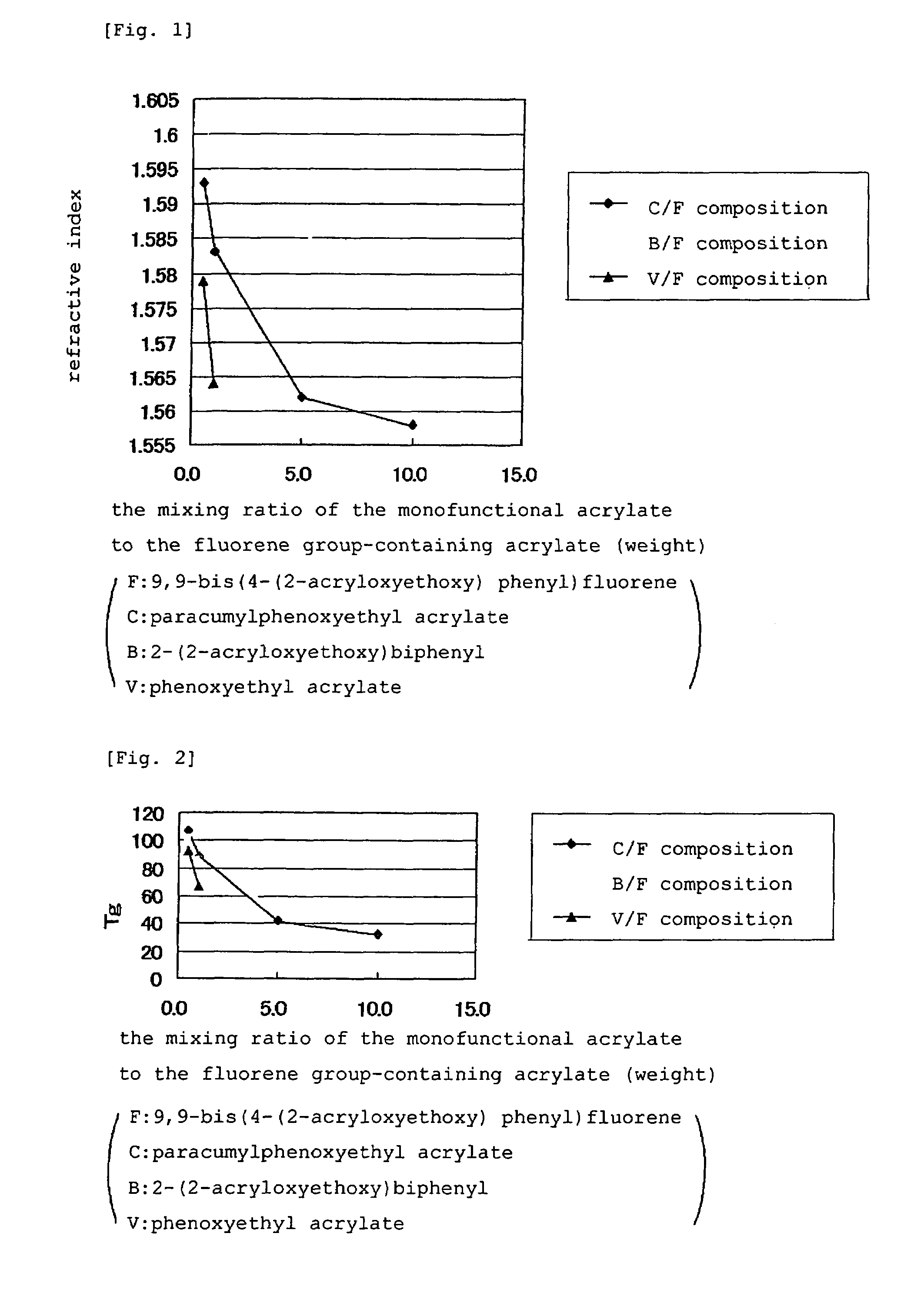
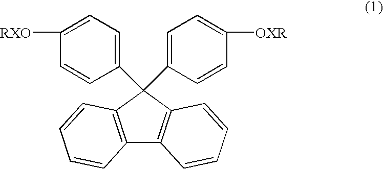
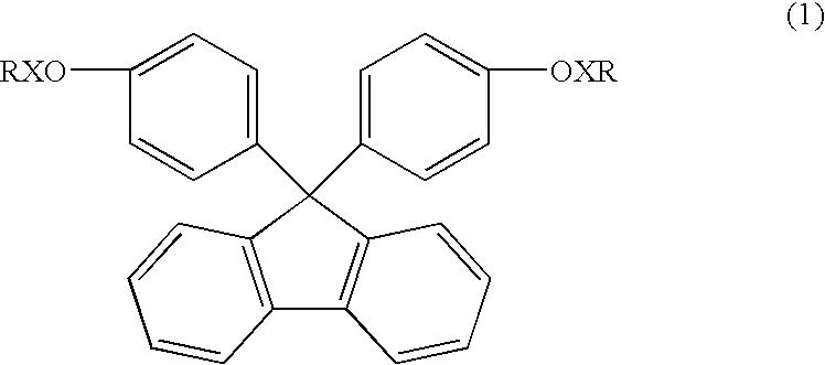
[0058]80 parts by weight of 9,9-bis(4-(2-acryloxyethoxy)phenyl)fluorene (Osaka Gas Chemicals Co., Ltd., product name: BPEF-A) was mixed with 20 parts by weight of paracumylphenoxyethyl acrylate (TOAGOSEI CO., LTD., product name: ARONIX M110), and the mixture was uniformly stirred at 60° C. and then cooled to 40° C. Subsequently, 1 part by weight of a curing agent (product of NOF CORPORATION, PERHEXA O) was added and uniformly dispersed by means of a planetary mixer, whereby a resin composition was obtained.

(2) Production of Cured Product Sheet

[0059]The resin composition obtained in (1) was sandwiched between two mold-releasing films composed of PET. After the thickness of the resin composition was adjusted, the resin composition was then heat-treated in an oven at 80° C. for 1 hour in order to cure it. Subsequently, the resin composition was cooled to room temperature, and the mold-releasing films were then removed, whereby a sheet of the cure...

examples 2 to 6

[0072]The same procedure as in Example 1 was repeated except that the amounts of 9,9-bis(4-(2-acryloxyethoxy)phenyl)fluorene and paracumylphenoxyethyl acrylate were changed as listed in Table 1 and that Irgacure I-651 (Ciba Specialty Chemicals) was used as the curing agent, to thereby prepare resin compositions. In addition to this, each of the obtained resin compositions was irradiated with light from a halogen lamp with a total light dose of 1 J / cm2 in order to cure it, whereby a sheet of the cured product was produced. Then, the sheet of cured product was evaluated. The results are shown in Table 1.

examples 7 to 11

[0073]The same procedure as in Example 2 was repeated except that 2-(2-acryloxyethoxy)biphenyl (product of TOAGOSEI CO., LTD., product name: T01463) was used in an amount listed in Table 1 in place of paracumylphenoxyethyl acrylate, to thereby prepare resin compositions. Then, a sheet of the cured product of each of the obtained resin compositions was produced and was evaluated. The results are shown in Table 1.


PUM

PropertyMeasurementUnit
refractive indexaaaaaaaaaa
glass transition pointaaaaaaaaaa

Abstract

A resin composition having a viscosity suitable for encapsulating optical devices such as light-emitting devices is provided. Specifically, the cured product of the resin composition has a refractive index greater than or equal to that of epoxy resins, exhibits excellent heat resistance and light resistance, and has thermal stress relaxation properties. The curable resin composition contains a fluorene group-containing acrylate or methacrylate represented by the following formula and a specific monofunctional acrylate or methacrylate:wherein X is —(CH2CH2O)n— or —(CH2CH2O)—CH2CH(OH)CH2O— with n being 1 to 5 and R is an acrylic or methacrylic group.

Description

BACKGROUND OF THE INVENTION[0001]1. Field of the Invention[0002]The present invention relates to a curable resin composition useful for encapsulation or the like of optical devices such as light-emitting devices.[0003]2. Description of the Related Art[0004]Traditionally, bisphenol A glycidyl ether type epoxy resins are used for encapsulating LEDs. However, such resins exhibit inferior heat resistance and light resistance (in particular, with regard to resistance to both UV and blue light). Hence, when these resins are used in high-intensity LEDs, UV LEDs, or the like, the resins are discolored by the heat and light emitted from the LEDs.[0005]Therefore, a problem exists in that the luminance of LEDs varies over time.[0006]In response to this problem, highly transparent epoxy resins have been developed. However, the heat resistance and light resistance of such resins are still not satisfactory.[0007]In view of the above, gel-type silicone resins have been used in high-intensity LEDs ...

Claims


Application Information

Patent Timeline
Patent Type & Authority Patents(United States)
IPC IPC(8): C08F222/14C08F2/46
CPCC08F220/30C08F222/1006C08F220/301
Inventor SAMUKAWA, HIROSHIHATSUDA, KOUKIIKEDA, YOSHITOANDO, HISASHIYAMAMOTO, NORIKAZU
Owner SONY CORP
Why Eureka
Try Eureka