Diffractive interferometric optical device for measuring spectral properties of light

Inactive Publication Date: 2008-12-16
CAMPUS TECH
View PDF10 Cites 13 Cited by
  • Summary
  • Abstract
  • Description
  • Claims
  • Application Information

AI Technical Summary

Benefits of technology

[0037]The particular advantages of the invention include a high-resolution and very compact optical spectrometer apparatus. The features of high-resolution and compactness result from an optical mono-mode coupling which guarantees unlimited spatial coherence without any need to employ optical arrangements involving e.g. the translation invariance of the Fourier transform. This fact also precludes the need for a collimator. The apparatus can therefore be

Problems solved by technology

The mechanical components for the setting of the optical path lengths by moveable mirrors or tiltable mirror pairs and the required collimator for the generation of planar wavefronts are above all technically demanding here.
The fact is disadvantageous for these interferometric spectrometers (both for Michelson/Twyman Green interferometers with variable wavelengths and for static interferometers with spatial interference patterns) that the relative spectral resolution is determined directly by the number of the line pairs (Fizeau stripes) measured in the interference patterns.
Fo

Method used


Image

  • Diffractive interferometric optical device for measuring spectral properties of light
  • Diffractive interferometric optical device for measuring spectral properties of light
  • Diffractive interferometric optical device for measuring spectral properties of light

Examples


first embodiment

III. First Embodiment

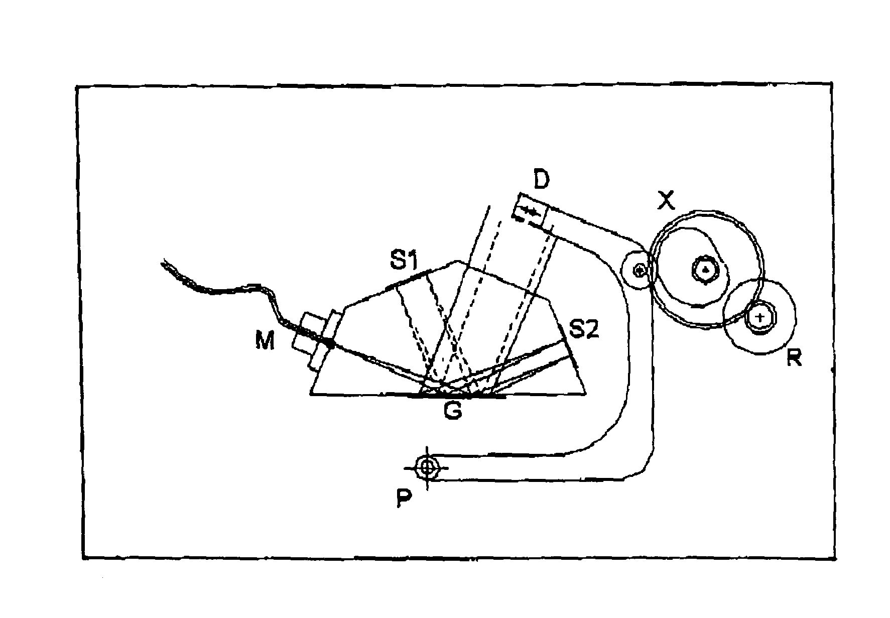
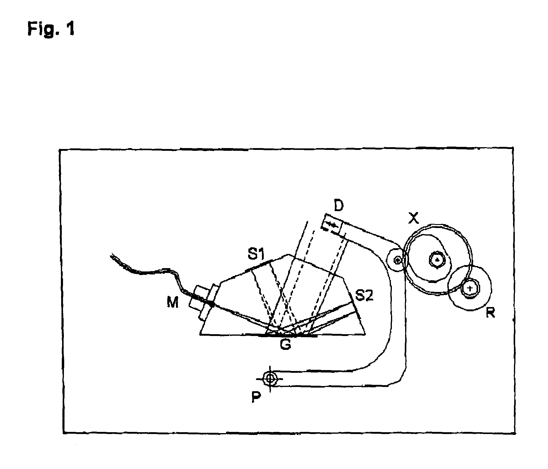
[0080]FIG. 1 illustrates an extremely compact arrangement of the apparatus of the invention with the optical components being integrated in a monolithic glass block.

[0081]According to the invention there is means (M) for coupling in one single spatial mode of an incoming light field. In the shown embodiment said means for coupling in a single mode is implemented using an optical mono mode fibre.

[0082]In the shown very compact setup the optical elements (M—mono mode coupler, G—grating, s1—Mirror, s2—Mirror) are shown fixed on a pentagonal mount. The mount may be made of glass or a suitable transparent material.

[0083]The light coupling (M) takes place directly from said mono-mode fiber into the monolithic glass block.

[0084]The incoming single spatial mode of light is directed to a grating (G). The grating is used as a beam splitter causing the incoming single spatial mode to be split according to amplitude into two partial fields.

[0085]The grating creates one part...

second embodiment

IV. Second Embodiment

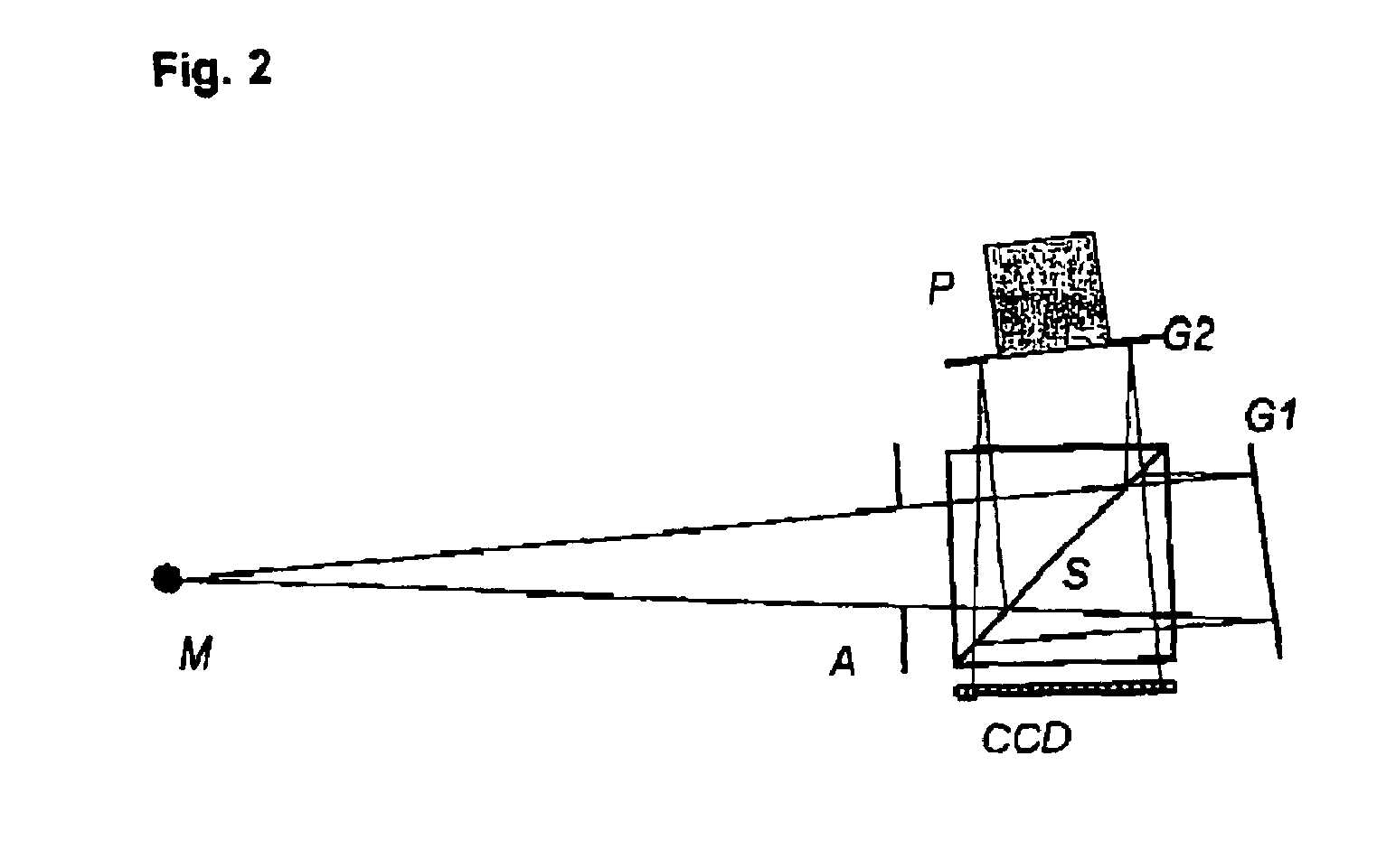
[0098]Referring now to FIG. 2, there is shown an arrangement that uses a separate beam splitter (S) for the division of the amplitude of the waves and two dispersive elements (G1, G2) in the arms of the interferometer.

[0099]According to the invention there is means (M) for coupling in one single spatial mode of an incoming light field. In the shown embodiment said means is a spatial filter i.e. implemented as pinhole.

[0100]Said incoming single spatial mode of light is directed to a beam splitter (S) passing an aperture (A). An aperture diaphragm (A) as shown is advantageous to limits the numerical aperture of the incoming light in order to avoid stray light.

[0101]The shown beamsplitter is implemented as cubic splitter using a semitransparent mirror. The incoming single spatial mode of light is split by amplitude into two partial fields.

[0102]One of the partial fields is the part of the field passing the semitransparent mirror. This partial field is directed to a...

third embodiment

V. Third Embodiment

[0111]The embodiments shown above are advantageous because they are not dependent on imaging optical elements.

[0112]Another advantage of the invention resulting from coupling in a single spatial mode is the possibility to employ means for dividing the wavefront of the single spatial mode to generate the partial fields. One skilled in the art will recognize advantages associated with using a wave front splitter instead of an amplitude splitter to allow for a broad range of new advantageous embodiments.

[0113]Referring now to FIG. 3, there is shown an arrangement that uses a wavefront splitter based on two optical gratings (G1,G2) for the division of the wavefront while said gratings (G1,G2) at the same time are used as spectrally dispersive elements.

[0114]According to the invention there is means (M) for coupling in one single spatial mode of an incoming light field. In the shown embodiment said means is a spatial filter i.e. implemented as pinhole.

[0115]In the arra...


PUM


Abstract

A diffractive interferometric optical device is provided for measuring spectral properties of light. The device includes means for coupling in a single spatial mode of an incoming light field to be examined, means for splitting the single spatial mode of incoming light field into at least two partial fields, means for changing one of a shape or a direction of propagation of the wavefront of at least one of the at least two partial fields in dependence on the wavelength and means for generating an interference pattern superimposing the at least two partial fields. The device further comprises detection means to record and evaluate the interference pattern at a plurality of discrete spatial positions in order to derive spectral properties of the incoming light field.

Description

BACKGROUND OF THE INVENTION[0001]1. Field of the Invention[0002]The invention relates to apparatus and methods related to optical spectroscopy and to optical sensors.[0003]2. Description of the Related Art[0004]Optical spectrometers can be generally divided into dispersive or diffractive spectrometers and Fourier transform spectrometers. Dispersive (prism) spectrometers or diffractive (grating) spectrometers break down the incident light beam into its spectral components by the wavelength dependence of an angle of deflection or of an angle of reflection. The different spectral components are thereby spatially separated and the spectral component to be determined can be selected (monochromator). The detection of a spectrum then takes place with the help of moving parts in that the different spectral components are selected and measured in succession.[0005]Monchromators are most common with a Czerny-Turner beam path, i.e. with a rotatable planar grating (diffraction grating in reflect...

Claims


Application Information

Patent Timeline
IPC IPC(8): G01B9/02G01J3/12G01J3/14G01J3/18G01J3/32G01J3/36G01J3/45G01J3/453
CPCG01J3/453
Inventor WEITZEL, THILO
Owner CAMPUS TECH
Why Eureka
Try Eureka