Digital servo control unit and laser machining apparatus
a servo control unit and laser machining technology, applied in the direction of electric programme control, program control, instruments, etc., can solve the problems of inability to accurately follow the current command signal, abnormal pulse width modulation of pmw control, and saturated supply voltage of power transistors, so as to reduce the cost of parts of the apparatus and reduce the stability margin of servo control
- Summary
- Abstract
- Description
- Claims
- Application Information
AI Technical Summary
Benefits of technology
Problems solved by technology
Method used
Image
Examples
first embodiment
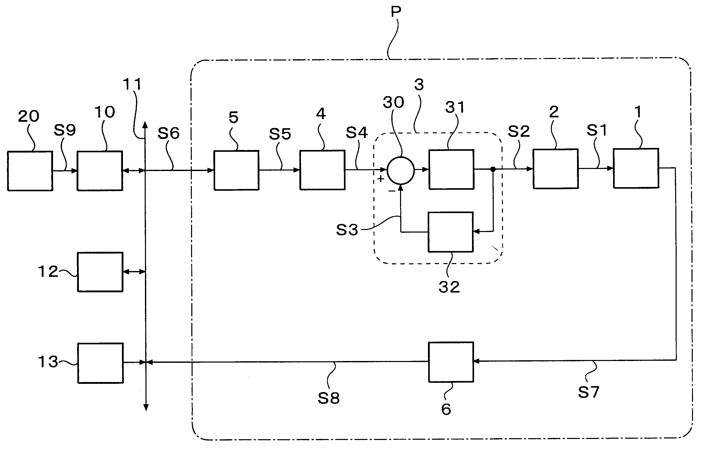
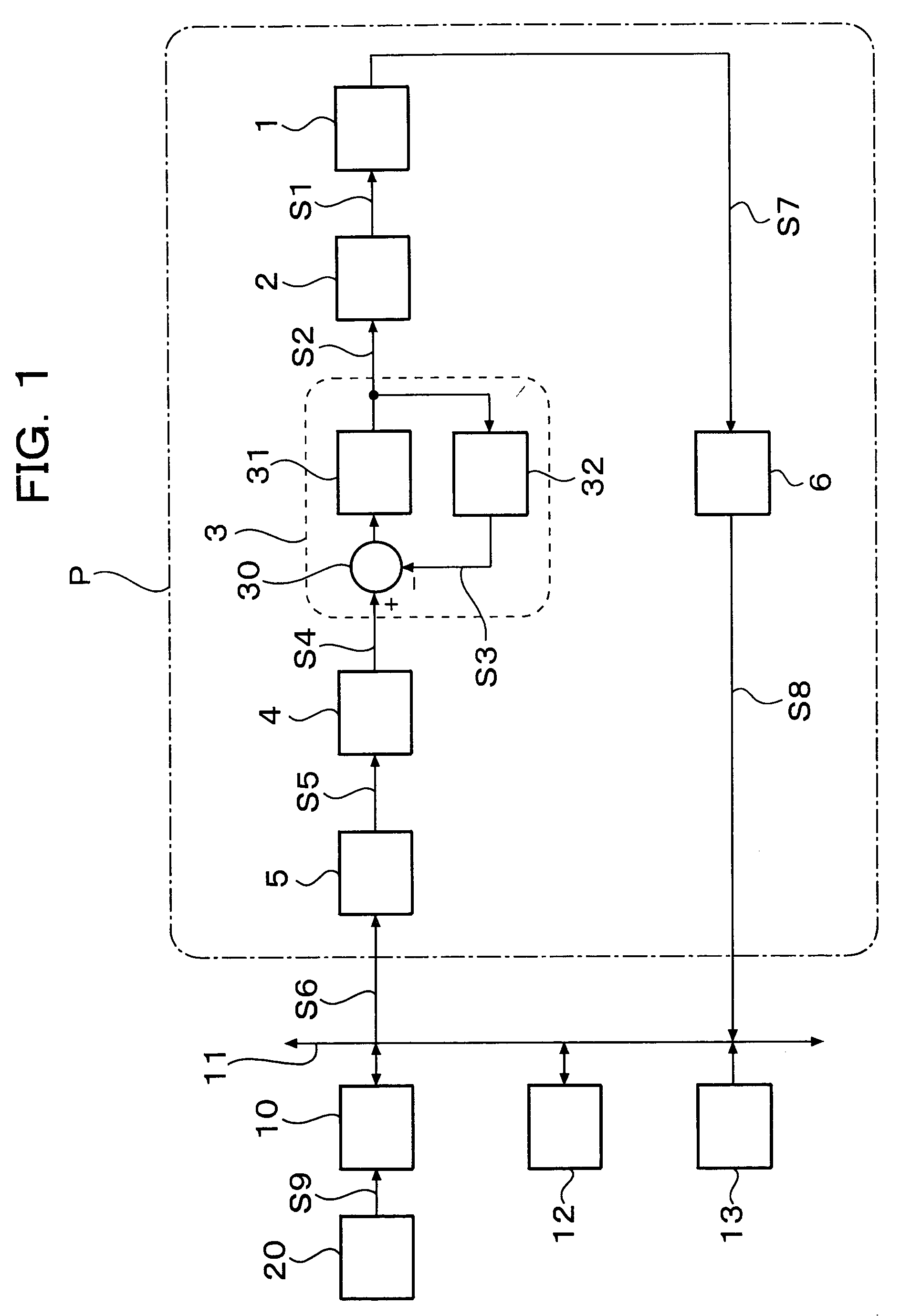
[0030]FIG. 1 is a block diagram of a digital servo control unit according to the present invention.
[0031]This control unit is a unit for digitally controlling the operation of a positioning mechanism 1 by a processor 10. The positioning mechanism 1 is driven by an actuator 2. When the present invention is applied to a digital servo control unit for a steerable mirror, the actuator 2 is a rotary electromagnetic actuator. The steerable mirror is fastened to the rotating shaft of the positioning mechanism 1. The positioning mechanism 1 is a rotor mechanism rotating in accordance with the driving torque generated by the actuator 2.
[0032]The processor 10 is connected to a D / A converter 5, an encoder 6, a random access memory (RAM) 12 and a read only memory (ROM) 13 through a bus 11.
[0033]A host controller 20 transmits an target position signal S9 of positioning operation to the processor 10. The encoder 6 detects a displacement S7 of the positioning mechanism 1 and outputs a discrete-tim...
second embodiment
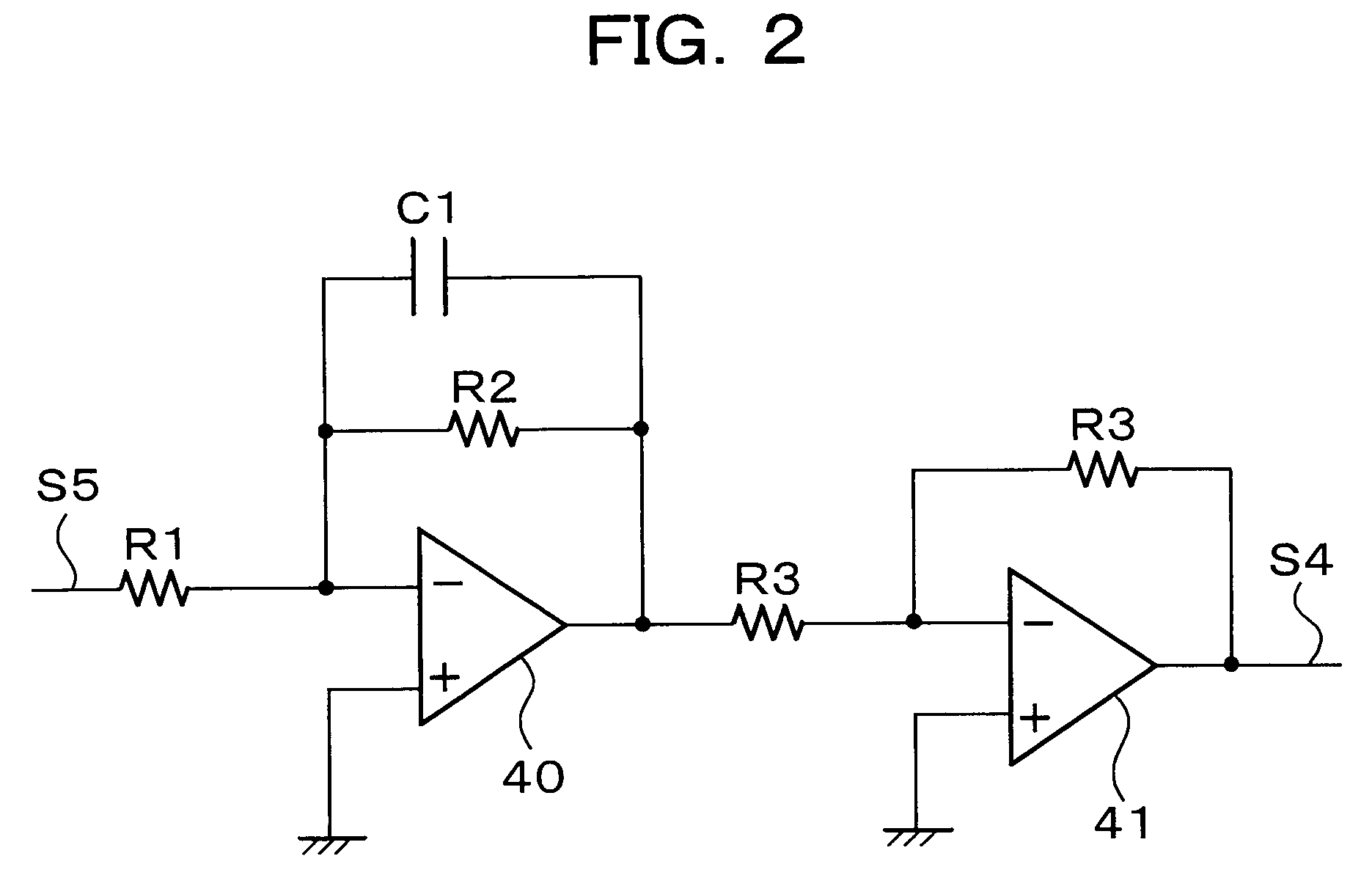
[0073]Although the current command signal S4 is smoothed by the first-order low pass filter 4 in the aforementioned first embodiment, this may be replaced by a second-order low pass filter. Here, when ωLP2 designates a cut-off frequency, ζLP2 designates a damping ratio and kLP2 designates a coefficient deciding a DC gain, a transfer function in the case of a second-order low pass filter is expressed by Expression 13.
[0074]GLP2(s)=kLP2s2+2ζLP2ωLP2s+ωLP22(13)
[0075]Though not shown, this second-order low pass filter can be also constituted by a simple operational amplifier circuit. In the same manner as in the first embodiment, the cut-off frequency is set to be lower than the sampling frequency. The configuration of the servo compensator is similar to that of FIG. 5, but the second-order low pass filter has two state variables. Therefore, the state observer 102 estimates the two state variables, and the estimated state variables are multiplied by state feedback coefficie...
third embodiment
[0076]Although the current command signal S4 is smoothed by the low pass filter in the aforementioned first and second embodiments, this may be replaced by a notch filter. Here, when ωN designates a cut-off frequency, ζNd designates a damping ratio of a denominator, and ζNn designates a damping ratio of a numerator, a transfer function in the case of a notch filter is expressed by Expression 14.
[0077]GN(s)=s2+2ζNnωNs+ωN2s2+2ζNdωNs+ωN2(14)
[0078]Though not shown, this notch filter can be also constituted by a simple operational amplifier circuit. In this event, it is intended to suppress spike-like pulsation as shown in FIG. 8B. It is therefore rational to make the cut-off frequency equal to the sampling frequency or an integer multiple of the Nyquist frequency. In order to remove harmonic components of the pulsation, a plurality of notch filters having different cut-off frequencies may be connected in series. Alternatively, a notch filter and a low pass filter may be used toge...
PUM
 Abstract
Description
Claims
Application Information
 - R&D
- Intellectual Property
- Life Sciences
- Materials
- Tech Scout
- Unparalleled Data Quality
- Higher Quality Content
- 60% Fewer Hallucinations
Browse by: Latest US Patents, China's latest patents, Technical Efficacy Thesaurus, Application Domain, Technology Topic, Popular Technical Reports.
© 2025 PatSnap. All rights reserved.Legal|Privacy policy|Modern Slavery Act Transparency Statement|Sitemap|About US| Contact US: help@patsnap.com


