Method and apparatus for selective filtering of ions
- Summary
- Abstract
- Description
- Claims
- Application Information
AI Technical Summary
Benefits of technology
Problems solved by technology
Method used
Image
Examples
example 1
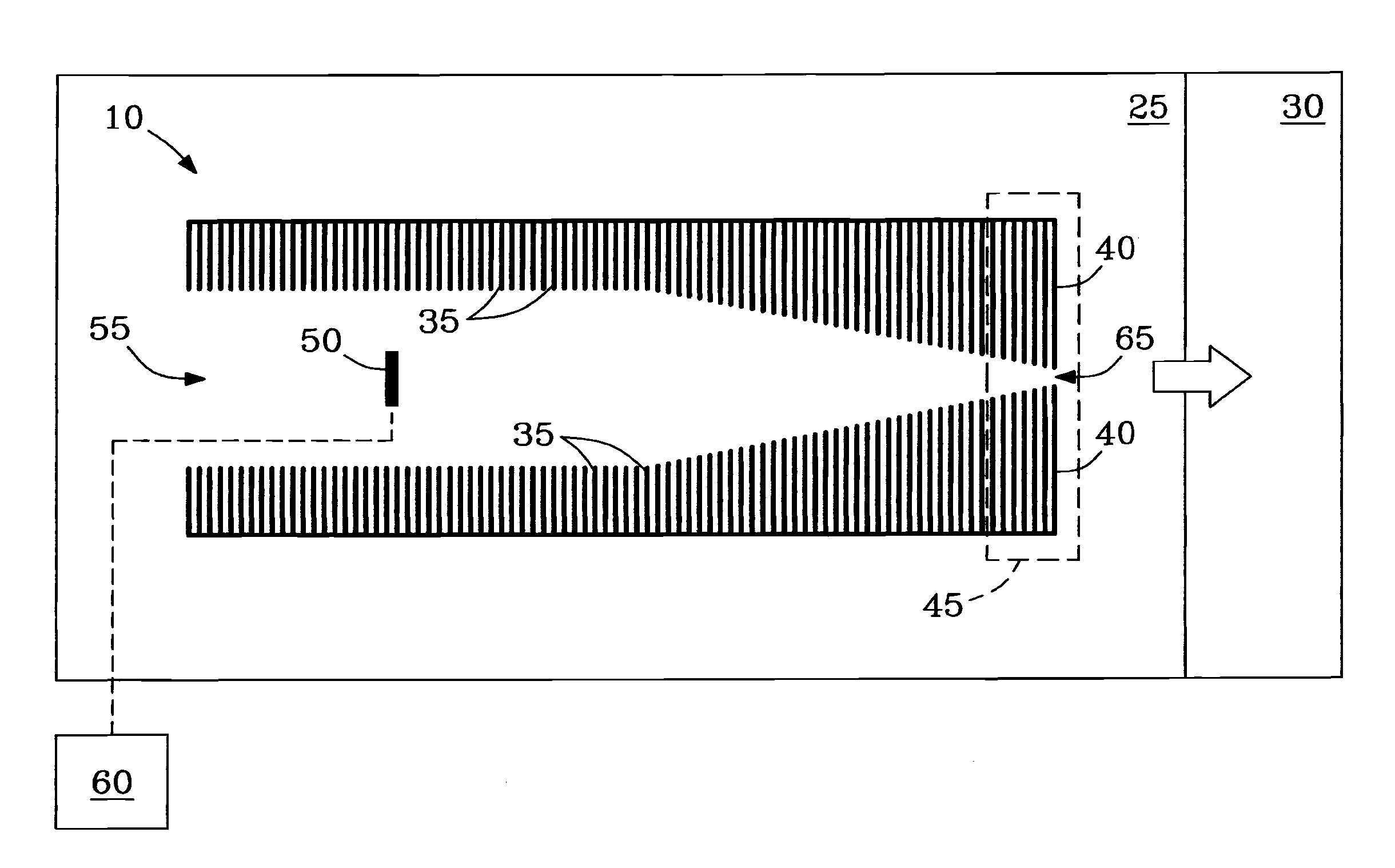
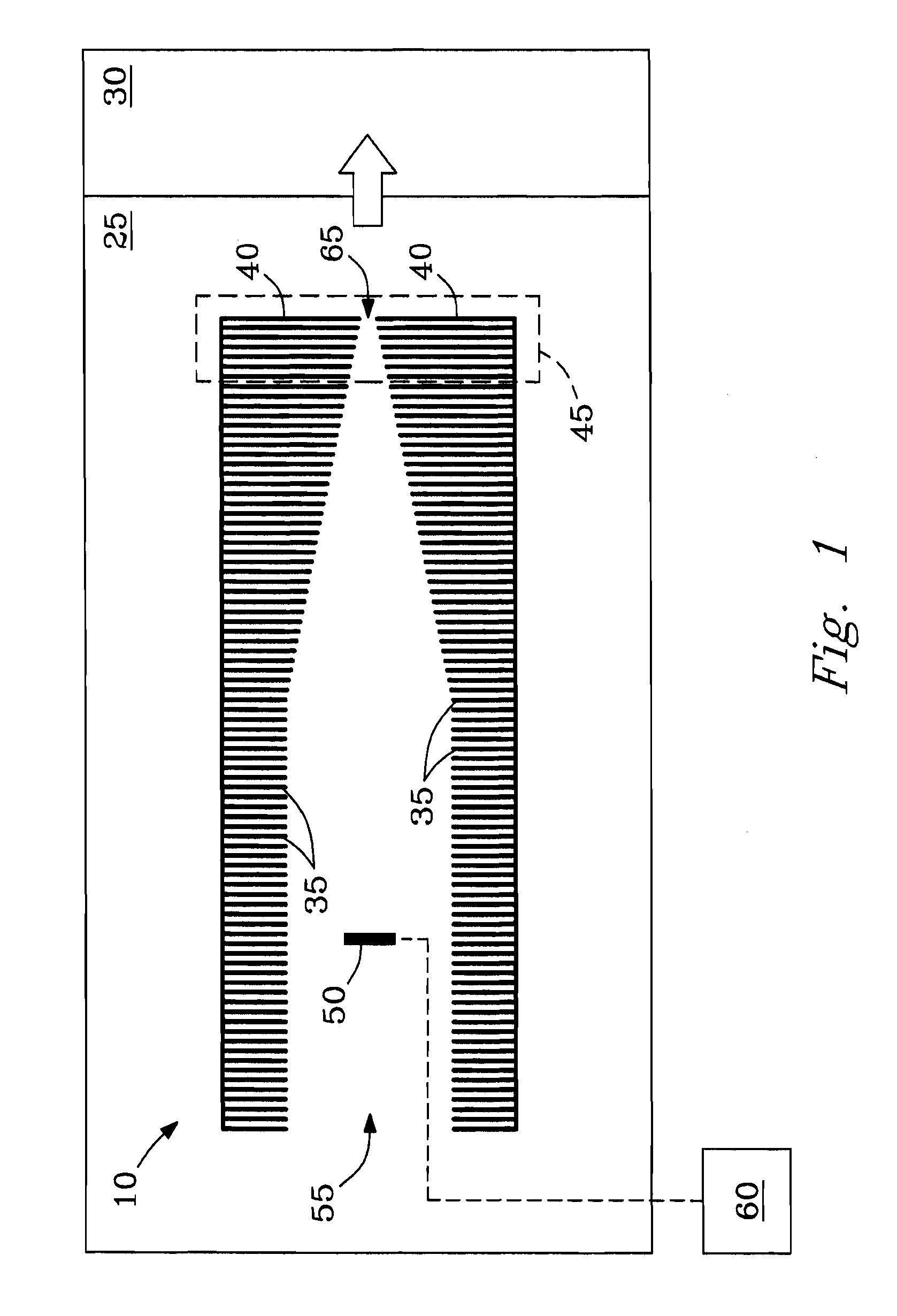
[0043]Example 1 describes tests showing ability of the conductance limiting electrode 40 of ion funnel 10 to perform selective low-mass filtering, e.g., as a low m / z filter 40.
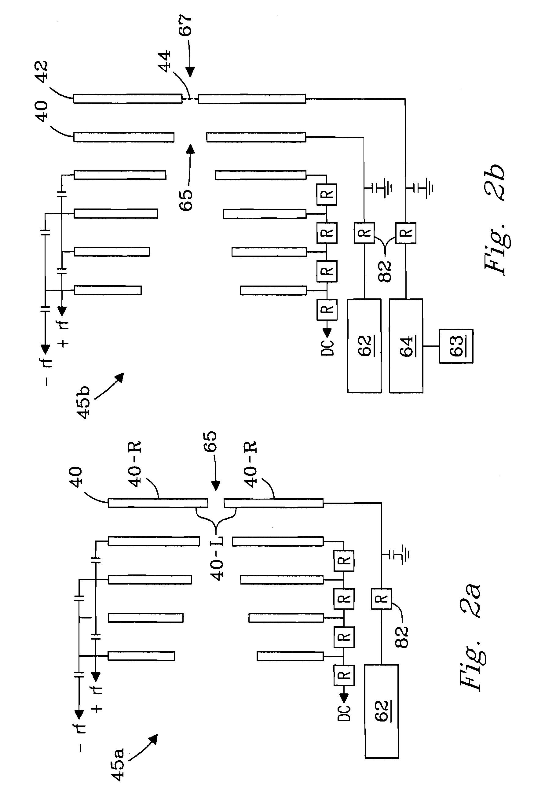
[0044]Ability of conductance limiting electrode 40 of ion funnel 10 to perform selective low-mass filtering was tested on a single quadrupole mass spectrometer (e.g., model 1100 quadrupole MS, Agilent, Palo Alto, Calif., USA) modified with an ESI / ion funnel source. The ESI / ion funnel configuration described in reference to FIG. 2b was employed. Ion funnel 10 was operated by applying an RF voltage of 500 kHz at 90 V peak-to-peak (90 Vp-p), but was not limited thereto. DC voltage applied to funnel plates 35 of ion funnel 10 yielded a constant gradient of 200 V at inlet 55 down to 5 V at exit aperture 65 of ion funnel 10. Pressure in funnel 10 was 1.9 Torr. ESI emitters were made by pulling sections of 100-μm i.d. / 200-μm o.d. fused silica capillary (Polymicro Technologies, Phoenix, Ariz., USA) either by hand with...
example 2
[0046]Example 2 describes tests relating m / z cut-off of filter plate 40 to the potential applied to filter plate 40 necessary to achieve filtering of low m / z ions.
[0047]A solvent mixture was prepared by combining methanol (Fisher Scientific, Pittsburgh, Pa., USA) and water (Nanopure Infinity Purification system, Barnstead, Dubuque, Iowa, USA) in a 50:50 ratio by volume and adding 1% by volume acetic acid (Sigma-Aldrich, St. Louis, Mo., USA). Filtering capacity of filter plate 40 was characterized by infusing and electrospraying (i.e., using an ESI / ion funnel source 25) the solvent mixture and acquiring mass spectra with the instrument described in Example 1. By observing the m / z cut-off at which chemical noise in the acquired mass spectra was eliminated, cut-off threshold could be ascertained as a function of voltage applied to filter plate 40. Filter plate 40 voltages were adjusted in one-volt increments in the range from about 12 V to about 18 V.
[0048]FIG. 4a presents a mass spect...
example 3
[0051]Example 3 describes the distribution of DC voltages and electric fields generated in the region near exit aperture 65 of filter plate 40 at an applied voltage of 15 V to filter plate 40. The DC electric field E was estimated using calculations based on the geometry shown in FIG. 1. As illustrated, e.g., in FIG. 2a, filter plate 40 can be considered a 3-dimensional plate having left and right surface planes (surfaces) 40-L and 40-R, respectively, and any suitable thickness (e.g., 0.5 mm), the left surface plane 40-L facing into the interior of ion funnel 10.
[0052]FIG. 5a shows the distribution of DC potentials observed for radial distances (r) of 0, 0.25, 0.5, 0.75 and 1 mm, respectively from the center of exit aperture 65 of filter plate 40 toward the radial edge of aperture 65 of filtering plate 40 as a function of axial coordinate “z” for rear section 45 of funnel 10. The origin of axial coordinate “z” is positioned at left-most surface plane 40-L (left surface) of filter pl...
PUM
 Abstract
Description
Claims
Application Information
 - R&D
- Intellectual Property
- Life Sciences
- Materials
- Tech Scout
- Unparalleled Data Quality
- Higher Quality Content
- 60% Fewer Hallucinations
Browse by: Latest US Patents, China's latest patents, Technical Efficacy Thesaurus, Application Domain, Technology Topic, Popular Technical Reports.
© 2025 PatSnap. All rights reserved.Legal|Privacy policy|Modern Slavery Act Transparency Statement|Sitemap|About US| Contact US: help@patsnap.com


