

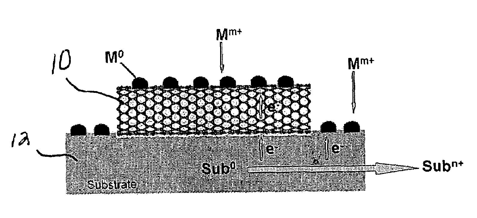
Substrate-enhanced electroless deposition (SEED) of metal nanoparticles on carbon nanotubes
a technology of carbon nanotubes and electroless deposition, which is applied in the direction of physical/chemical process catalysts, cell components, liquid/solution decomposition chemical coatings, etc., can solve the problem of limited general applications of electroless deposition
- Summary
- Abstract
- Description
- Claims
- Application Information
AI Technical Summary
Benefits of technology
Problems solved by technology
Method used
Image

Examples
example 1
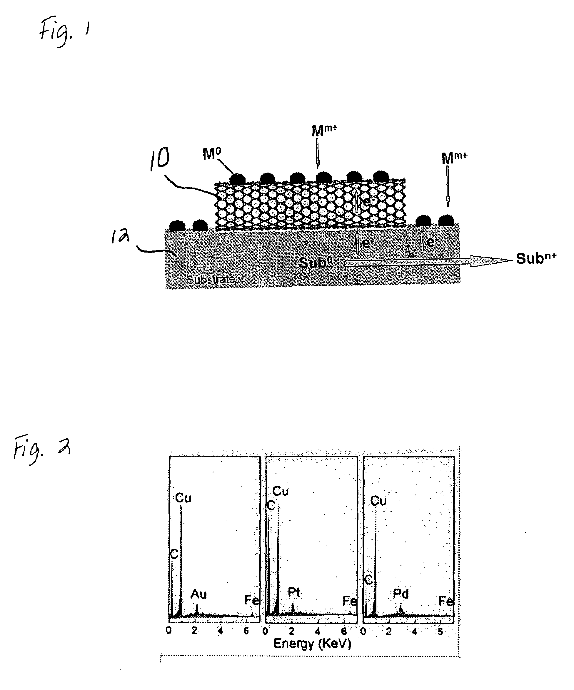
[0029]Multi-walled carbon nanotubes were prepared by pyrolysis of iron (II) phthalocyanine (FePc). A scanning electron microscopy (Philips XL30 FEG) image of the FePc-generated multi-walled nanotubes randomly dispersed on a copper foil support (EMS US), showed that the pristine nanotubes possessed a smooth surface and were almost free from pyrolytic impurities on the nanotube surface (e.g. amorphous carbon and residual catalyst nanoparticles). Upon immersion of the Cu-supported multi-walled carbon nanotubes into an aqueous solution of HAuCl4 (3.8 mM), Au nanoparticles spontaneously formed on the nanotube sidewalls. The SEM images taken at different stages during the process showed that the nucleation of Au nanoparticles started within seconds. Au clusters with a diameter of about 100 nm were clearly evident along the nanotube sidewalls after about 10 seconds of exposure to the HAuCl4 solution. Longer reaction times caused no obvious change in the particle size but caused a significa...
example 2
[0033]Pt metal nanoparticles having a cubic shape were deposited onto carbon nanotubes by immersing Cu-supported carbon nanotubes into an aqueous solution of K2PtCl4 under different conditions: 3.8 mM K2PtCl4 and 5 mM CuCl2 for 1 minute; 0.95 mM K2PtCl4 for 30 minutes. While not wishing to be bound to any theory, we believe that the Cu2+ ions act as a capping reagent to regulate the shape of the nanoparticles.
example 3
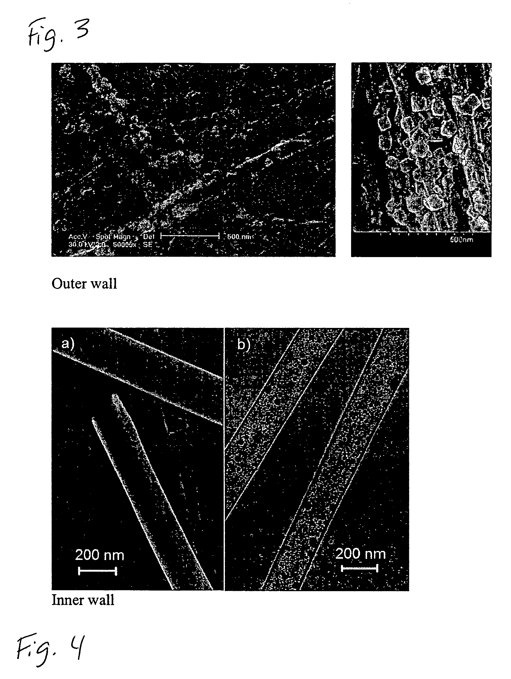
[0034]Pt nanoparticles in the shape of spheres were deposited onto the inner walls of carbon nanotubes. First, a template-synthesized, aligned carbon nanotubes contained within an alumina membrane were immersed into an aqueous solution of 1.9 mM K2PtCl4 under ultrasonication for 5 minutes. (The template-synthesized carbon nanotubes were prepared by pyrolysis of acetylene in an alumina membrane (about 200 nm) at 700° C.). After removing the remaining solution on the surface of the alumina membrane by adsorption with a filter paper, the alumina-membrane-supported aligned carbon nanotube film was perpendicularly anchored to a copper foil using tapes and then re-immersed the aqueous solution of 1.9 mM K2PtCl4 for 30 minutes, which resulted in the formation of Pt nanospheres on the nanotube inner wall (see FIG. 4). The modified carbon nanotubes were then released from the alumina membrane using an aqueous HF solution.
[0035]The modified carbon nanotubes were then supported on a Cu foil in...
PUM
| Property | Measurement | Unit |
|---|---|---|
| Time | aaaaa | aaaaa |
| Shape | aaaaa | aaaaa |
| Electrical conductor | aaaaa | aaaaa |
Abstract
Description
Claims
Application Information