Method and system for coating internal surfaces using reverse-flow cycling

a technology of reverse-flow cycling and internal surfaces, applied in the direction of solid-state diffusion coating, plasma technique, coating, etc., can solve the problem that thermal techniques cannot be used for substrates that are not heat-sensitive, and achieve the effect of providing uniform coating and efficiently coating workpieces

Inactive Publication Date: 2009-06-02
SUB ONE TECH
View PDF14 Cites 61 Cited by
  • Summary
  • Abstract
  • Description
  • Claims
  • Application Information

AI Technical Summary

Benefits of technology

[0008]A method in accordance with the present invention allows uniform coating of internal surfaces of a pipe, tube or other workpiece by using the workpiece itself as a deposition chamber and using flow reversal of coating material within the workpiece. The method includes coupling at least a first opening of the pipe to a gas supply subsystem to function as an entrance and coupling at least a second opening of the pipe to a pumping subsystem to function as the exit. In a first coating cycle, gas is flowed through the pipe from the first opening (entrance) to the second opening (exit). Then, with the pipe remaining in place, the flow of gas through the workpiece is reversed to accomplish a second coating cycle. In some embodiments, the method and the system for implementing the method are used to provide reverse-cycle coating for a workpiece with more than two openings. On the other hand, the reverse-cycle coating method may be applied to workpieces with a single opening, if the cycling is via a device that is inserted into the workpiece.
[0012]For the reverse-cycle coating process, the gas flow and the pumping speed preferably are adjusted such that the pressure provides a hollow cathode environment in the workpiece upon application of a voltage bias. This pressure is such that the electron mean free path is slightly less than the diameter of the tube, causing electrons to oscillate across the tube and resulting in multiple ionizing collisions and a more intense plasma. This provides an improvement relative to prior art PECVD approaches in which plasma is generated externally from a workpiece, resulting in a loss of ionization as gas flows through the tube, so that less film deposition occurs toward the exit from the workpiece. The hollow cathode effect, being dependent on pressure, the plasma density and consequently the film thickness and quality will vary along the length of the tube if the pressure drop across the tube becomes too large. In comparison, as a consequence of the flow reversal, the invention achieves a more uniformly ionized plasma along the length of the workpiece, thereby providing a more uniform deposition. Improvement in deposition uniformity is accomplished by controlling the pressure drop across the workpiece and implementing the reverse-cycle coating process to provide a uniform plasma.
[0013]The method allows coating of interior surfaces of pipes, tubes, valves, pumps or other workpieces with more complex geometries. While the openings may be referred to as “entrances” and “exits,” these roles are reversed when the direction of flow is reversed. The flow cycling significantly reduces the possibility of an end-to-end decline in coating thickness as a consequence of a gradual reduction of the density of coating material in the plasma as the coating material is drawn from the plasma to the internal surface or surfaces of the workpiece. The improvement of end-to-end coating thickness is also due to the gas reservoirs providing fresh reactant gas at each workpiece opening, that can flow or diffuse into the pipe as the gas is consumed or depleted within the pipe during the coating process.
[0015]In some embodiments, the biasing system is also cycled. A negative pulsed DC voltage is applied so as to have a duty cycle that is selected such that (1) when the voltage is “on,” a negative voltage is applied to the workpiece such that positive source gas ions are attracted to the internal surfaces and react chemically to coat the internal surfaces of the workpiece, and (2) when the voltage is “off,” the positive source gas ions are sufficiently replenished within the interior of the workpiece to provide uniformity in coating the internal surfaces. If the coating material is an insulator, the “off” condition of the duty cycle may include a reverse voltage that is sufficient to deplete surface charges resulting from the coating of the internal surfaces of the workpiece.
[0016]Where the workpiece includes at least two openings, anodes may be coupled to each opening, with the anodes being physically and electrically isolated from the workpiece by retractable seals. Also, a gas reservoir is coupled to each opening, such that the gas pressure at each opening can be controlled by means of the flow into the reservoir from the gas source and the flow out of the gas reservoir either into the pipe or to the pump. Thus, the pressure gradient across the pipe can be precisely controlled.
[0017]In another embodiment of the invention, a device is inserted into the workpiece and is used to implement the reverse-cycle coating method. The device includes at least one hole to enable gas flow to and from the device. In one cycle, the gas is flowed from the inserted device, through the conductive workpiece, and out an opening of the workpiece. This embodiment is particularly well suited for coating internal surfaces of a workpiece having a single opening. The flow of gas may be reversed, so that the flow is through the workpiece to the device. The device may include a tube that is adjustable in length and that includes a number of holes, with the number varying as the length is adjusted. This adjustability enables the device to be used to efficiently coat workpieces of various sizes.

Problems solved by technology

Thermal techniques can only be used for substrates that are not heat sensitive.

Method used


Image

  • Method and system for coating internal surfaces using reverse-flow cycling
  • Method and system for coating internal surfaces using reverse-flow cycling
  • Method and system for coating internal surfaces using reverse-flow cycling

Examples


Embodiment Construction

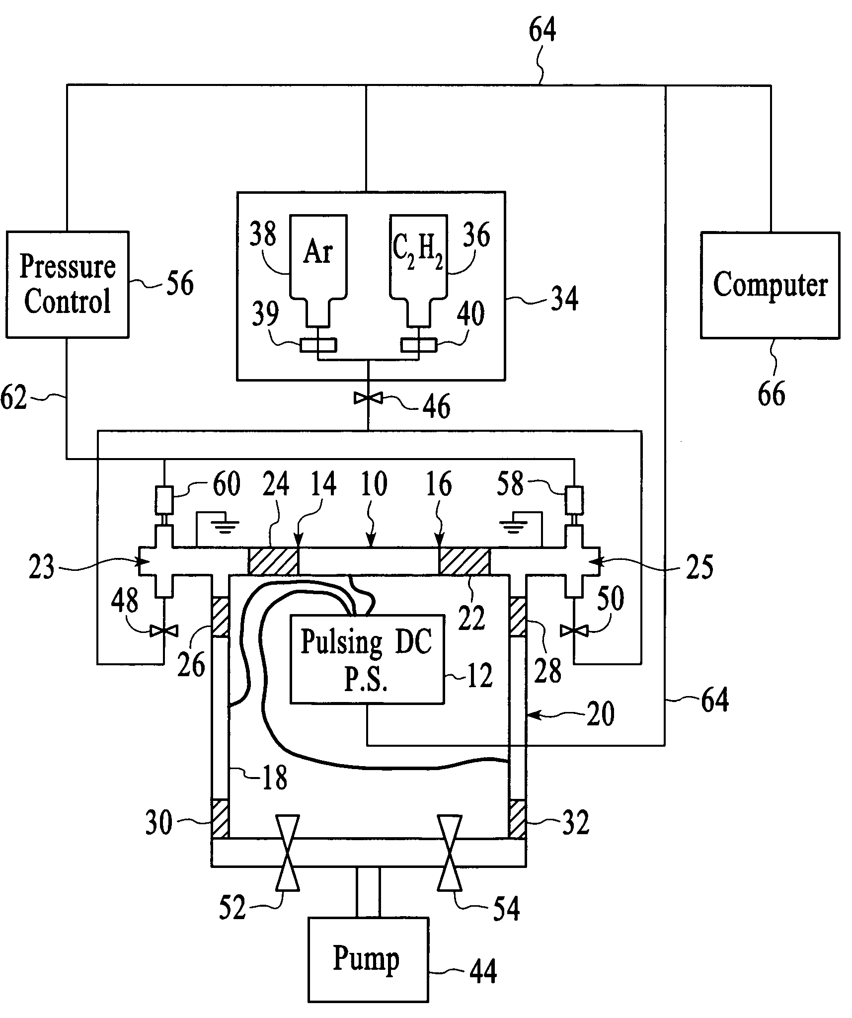
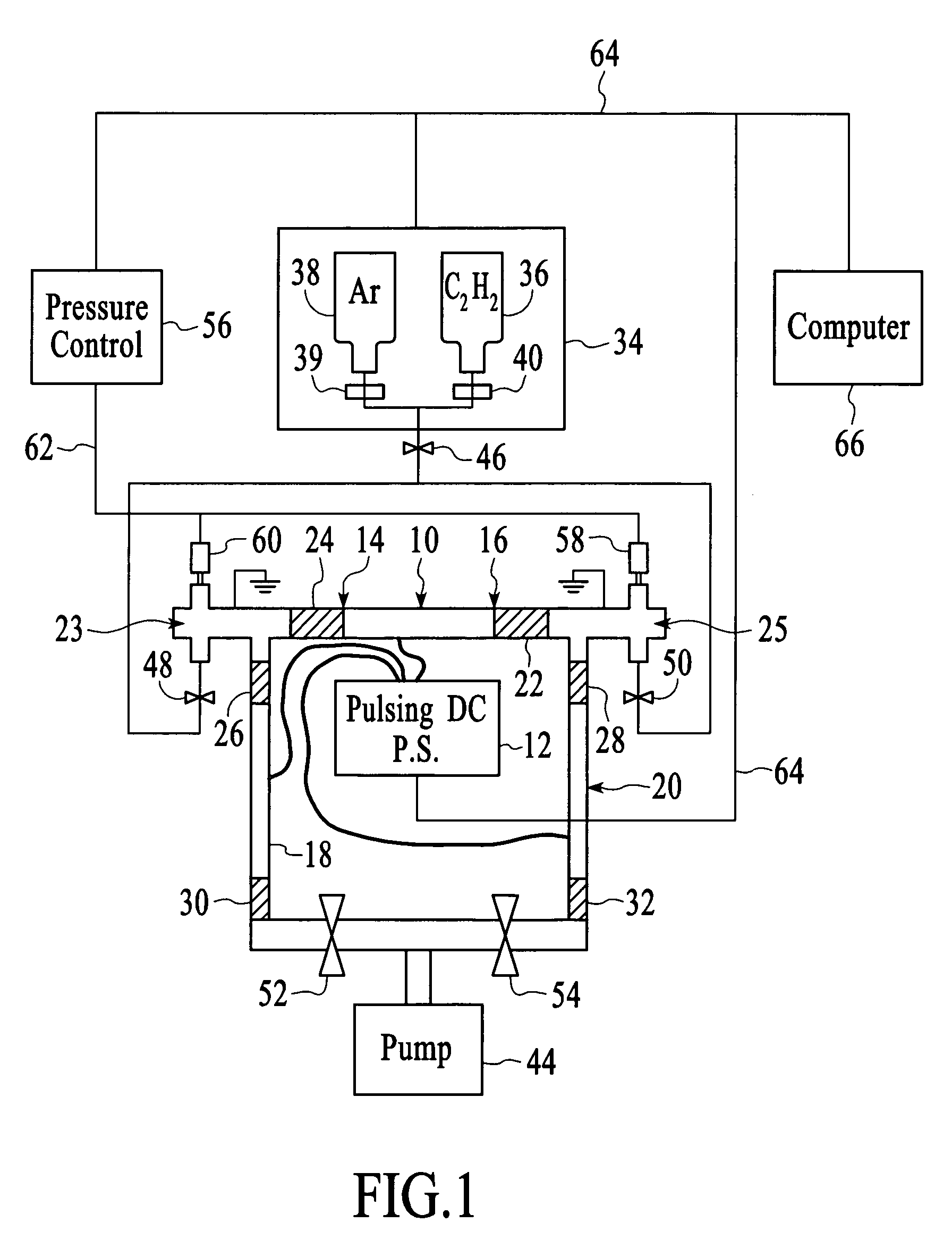
[0025]With reference to FIG. 1, a conductive pipe or “workpiece”10 is connected to a pulsed DC power supply 12, which applies a pulsed negative bias. This negative bias is used to (a) create a plasma between a cathode and an anode, (b) draw an ionized reactive gas to the surfaces to be coated, (c) allow ion bombardment of the film to improve film properties such as density and stress levels, and (d) allow control of uniformity by adjusting the duty cycle so as to permit replenishment of a source gas and depletion of surface charges resulting from the coating process during the “off” portion of the cycle. Here, the workpiece 10 functions as a cathode while anodes 18 and 20 are connected to the positive side of the pulsed DC supply. Gas reservoirs 23 and 25 are coupled to each end of the workpiece. In this embodiment, they are electrically isolated from the workpiece and grounded. In other embodiments, they can be biased as a cathode or allowed to float with the anodes grounded. Press...


PUM

PropertyMeasurementUnit
pressureaaaaaaaaaa
pressureaaaaaaaaaa
diameteraaaaaaaaaa

Abstract

A method and system for coating the internal surfaces of a workpiece is presented. A bias voltage is connected to a workpiece, which functions as a cathode. A gas source and a vacuum source are coupled to each opening through a flow control system. The flow control system is capable of a first mode which enables a first opening to function as a gas inlet and a second opening to function as a vacuum exhaust. The flow control system also has a second mode which enables a first opening to function as a vacuum exhaust and a second opening to function as a gas inlet. The cycling may also be used to coat internal surfaces of a workpiece with a single opening. Cycling the flow control system between the first mode and second mode is performed until a uniform coating along the internal surfaces of the workpiece is achieved.

Description

TECHNICAL FIELD[0001]The invention relates generally to chemical vapor deposition systems and more specifically to methods and systems for coating piping.BACKGROUND ART[0002]Much effort has been expended in improving the corrosion resistance of specialty metal alloys, for example stainless steel (SS), by precisely defining chemistry levels (e.g., 16 to 18% Cr in 316L SS) and decreasing impurity levels (e.g., less than 0.03% S and C in 316L SS) that remain after melting and refining. This requires specialized steel manufacturing methods, such as vacuum oxygen decarburization (VOD), vacuum induction melting (VIM) and vacuum arc remelting (VAR), which add significant cost. An additional problem with low impurity steel is that machinability, hardness and other relevant considerations can be negatively affected. Expensive post machining processing, such as burnishing and electropolishing, often must be performed in order to meet hardness and surface roughness requirements specified by or...

Claims


Application Information

Patent Timeline
Patent Type & Authority Patents(United States)
IPC IPC(8): C23C16/00H01L21/441
CPCC23C16/0245C23C16/0263C23C16/045C23C16/26C23C16/45502C23C16/45578C23C16/503C23C16/515
Inventor TUDHOPE, ANDREW WILLIAMBOARDMAN, WILLIAM JOHNMERCADO, RAUL DONATECONTRERAS, FREDERICK
Owner SUB ONE TECH
Why Eureka
Try Eureka