
Anode active material, manufacturing method thereof, and non-aqueous electrolyte secondary battery

a technology of anode active material and secondary battery, which is applied in the direction of non-aqueous electrolyte cells, alkali titanates, sustainable manufacturing/processing, etc., can solve the problems of reducing cycle life, difficult to maintain a flat charge/discharge voltage, and difficulty in maintaining cycle life by conventional techniques

Active Publication Date: 2009-06-02
OSAKA CITY UNIV +1
View PDF107 Cites 107 Cited by
  • Summary
  • Abstract
  • Description
  • Claims
  • Application Information

AI Technical Summary

Benefits of technology

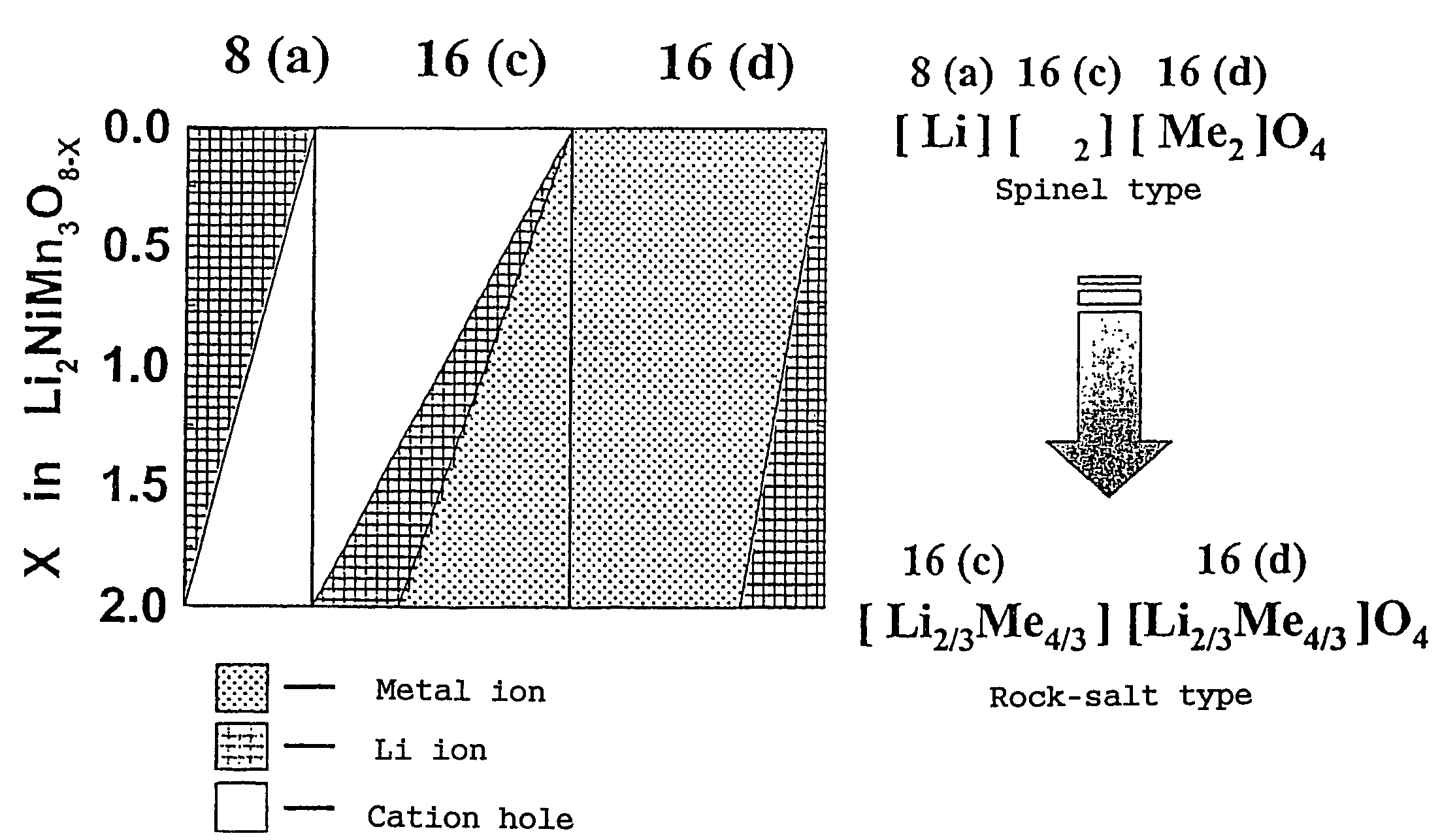
"The present invention relates to a positive electrode active material for non-aqueous electrolyte secondary batteries, which exhibits topotatic two-phase reactions during charge and discharge. The material is represented by the formula Li2±αMn4O8−x, where Mn is a transition metal containing at least one selected from the group consisting of Ni, Cr, Fe, Co and Cu. The material has a unique structure and is produced by a specific method involving mixing raw materials, synthesizing a eutectic compound, and subjecting it to a first baking at a high temperature. The material has a high energy density and is suitable for use in high-performance batteries. The non-aqueous electrolyte secondary battery using this material has a practical charging / discharging region of 2.5 to 3.5 V and a practical average voltage of 3V level. The battery has a potential difference of 0.2 to 0.8 V in an operating discharge voltage. The positive and negative electrodes are made of aluminum or an aluminum alloy, and the non-aqueous electrolyte can include various compounds such as propylene carbonate, γ-butyrolactone, γ-valerolactone, methyl diglyme, sulfolane, trimethyl phosphate triethyl phosphate, and methoxymethylethyl carbonate. The weight ratio of the negative electrode active material to the positive electrode active material is preferably not less than 0.5 and not greater than 1.2."

Problems solved by technology

Charging / discharging at a high rate imposes an increased load on the active material, making it difficult to maintain the cycle life by conventional techniques.
Accordingly, it is difficult to maintain a flat charge / discharge voltage during high rate charging / discharging.
Since the positive electrode active material repeatedly expands and contracts to a great degree in the layer direction during charging / discharging, the stress resulting therefrom reduces the cycle life particularly at the time of high rate charging / discharging.
However, from the viewpoint of determination of the remaining capacity, they are considered as not suitable for determining the remaining capacity because accurate analysis in a narrow potential range is necessary.
Accordingly, it is difficult that the above two is incorporated uniformly.
In addition, since the baking is performed at a high temperature of not less than 900° C., reactivity with lithium is reduced after the baking, making it difficult to obtain the desired positive electrode active material.
Some of the conventional techniques, however, cannot completely solve the above-mentioned problems such as improving high rate characteristics and pulse characteristics.
For example, charging / discharging at a high rate imposes an increased load on the active material to cause structural damage, thus making it difficult to maintain the cycle life.
In addition, since a lithium cobalt oxide and a graphite material, both having a layered structure, repeatedly expand and contract to a great degree in the layer direction during charging / discharging, a stress is given to the active material and an electrolyte exudes from between electrodes, thus reducing the cycle life particularly at the time of high rate charging / discharging.
The former has the problem that it should have a flatter voltage although it is not difficult to monitor the remaining capacity thereof.
In the case of the latter, on the other hand, the voltage difference is extremely small until the end of discharging, so that it is very difficult to monitor the remaining capacity of the battery.
Accordingly, obtaining a battery whose remaining capacity can be moderately monitored remains one of the problems.

Method used


Image

  • Anode active material, manufacturing method thereof, and non-aqueous electrolyte secondary battery
  • Anode active material, manufacturing method thereof, and non-aqueous electrolyte secondary battery
  • Anode active material, manufacturing method thereof, and non-aqueous electrolyte secondary battery

Examples


experiment 1

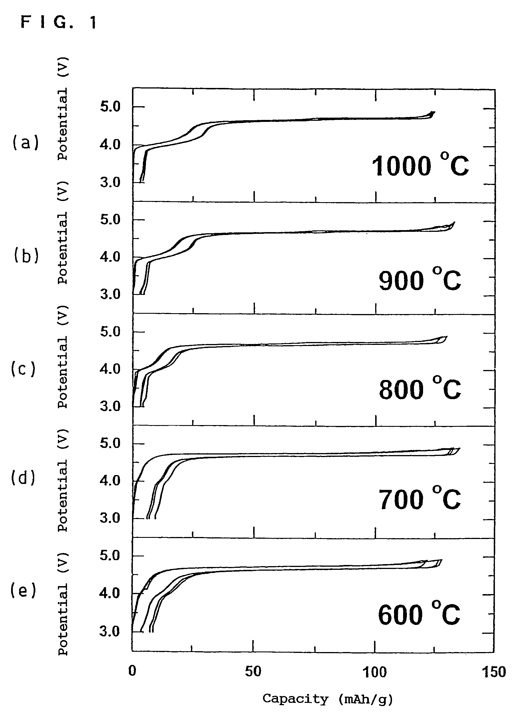
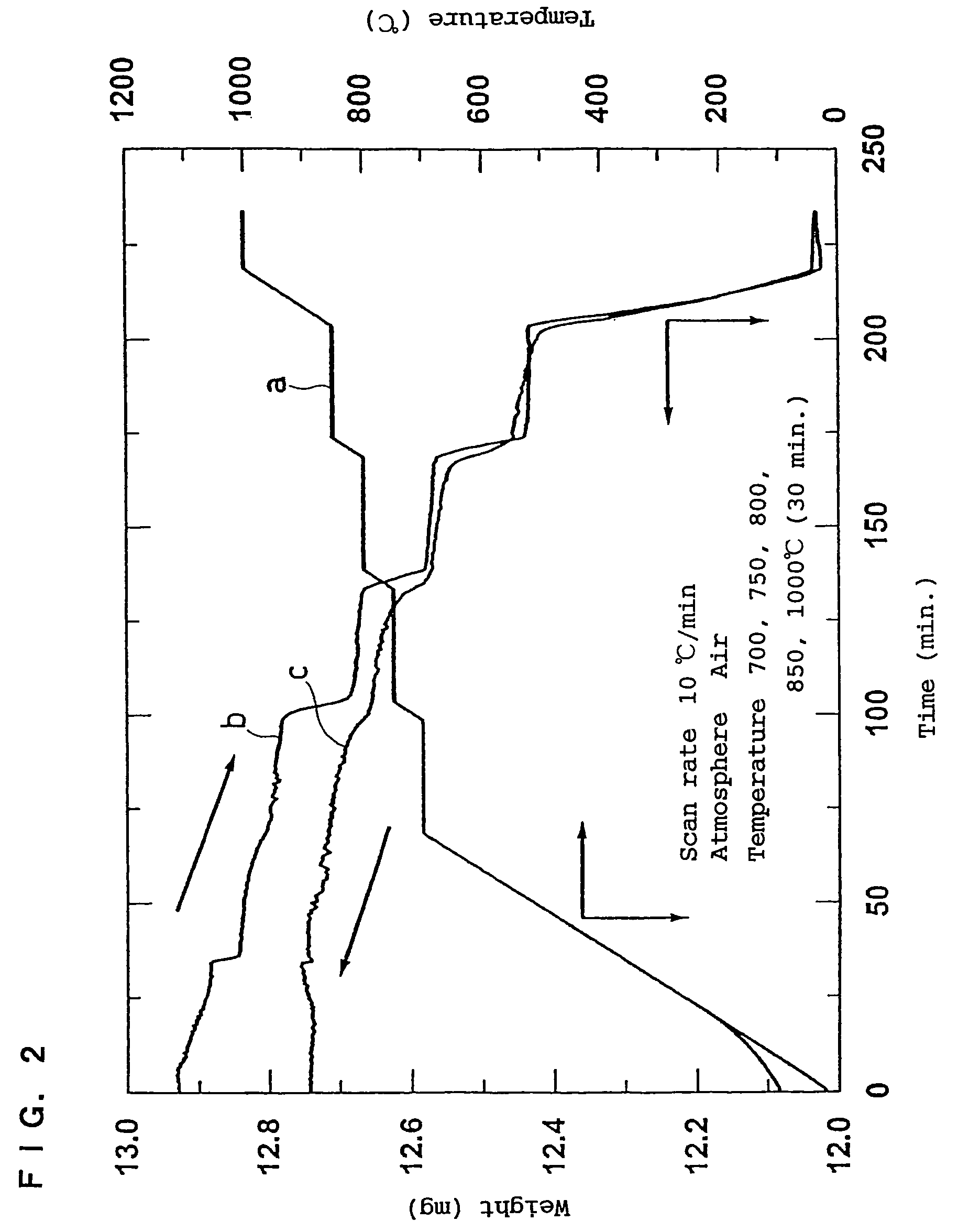
[0252]Three different types of positive electrode active material samples were prepared under the synthesis conditions shown in the above section (3). A mixture obtained by thoroughly mixing [Ni1 / 4Mn3 / 4](OH)2 obtained through a eutectic reaction and LiOH.H2O was formed into pellets, which was then baked to give a positive electrode active material. Accordingly, the composition of the obtained positive electrode active material was Li[Ni1 / 2Mn3 / 2]O4. The amount of oxygen was changed according to the synthesis condition. The electrochemical analysis of the obtained positive electrode active materials was performed in the manner shown in the above section (1).

(i) PRODUCTION EXAMPLE 1

[0253]The ambient temperature was increased from room temperature to 1000° C. for about 3 hours, maintained at 1000° C. for 12 hours and then decreased from 1000° C. to room temperature for 2 hours.

(ii) PRODUCTION EXAMPLE 1

[0254]The ambient temperature was increased from room temperature to 1000° C. for abou...

production example 1

(iii) PRODUCTION EXAMPLE 1

[0255]The ambient temperature was increased from room temperature to 1000° C. for about 3 hours, maintained at 1000° C. for 12 hours and rapidly cooled from 1000° C. to room temperature. Then, the ambient temperature was increased to 700° C. for about 1 hour, maintained at 700° C. for 48 hours and decreased from 700° C. to room temperature for 1.5 hours.

[0256]The electrochemical behaviors of the positive electrode active materials obtained in Production Examples 1 to 3 are shown as (a) to (c) in FIG. 22. Form FIG. 22, it is understood that all of the positive electrode active materials show small polarization and a flat charge / discharge curve. The positive electrode active material (a) of Production Example 1 exhibits a voltage difference at the end of discharging, which can be utilized for the detection of the remaining capacity. The difference is as small as only several V, so that the effective detection of remaining capacity can be achieved without the ...

experiment 2

[0260]A 3V level battery was produced using the positive electrode active material in accordance with the present invention in the positive electrode and a negative electrode active material Li4Ti5O12(Li[Li1 / 3Ti5 / 3]O4) in the negative electrode. The negative and positive electrode plates were produced in the same manner, using the same compound ratio. As the separator, a 25 μm non-woven fabric made of polybutylene terephthalate was used. The electrode area was set to 3 cm2. As the electrolyte, an organic electrolyte solution prepared by dissolving 1 mol of LiPF6 in a solvent mixture of EC and DEC in a ratio of 3:7 was used. The positive electrode active material used here was the one obtained in the above-mentioned Case 3.

[0261]FIG. 23 shows the discharge behavior of this battery system, and FIG. 24 shows the high rate characteristics of the same. FIGS. 23 and 24 illustrate that the battery system of the present invention is a 3V level battery with excellent polarization characteris...


PUM

PropertyMeasurementUnit
particle sizeaaaaaaaaaa
voltageaaaaaaaaaa

Abstract

In order to provide a 3V level non-aqueous electrolyte secondary battery with a flat voltage and excellent cycle life at a high rate with low cost, the present invention provides a positive electrode represented by the formula: Li2±α[Me]4O8−x, wherein 0≦α<0.4, 0≦x<2, and Me is a transition metal containing Mn and at least one selected from the group consisting of Ni, Cr, Fe, Co and Cu, said active material exhibiting topotactic two-phase reactions during charge and discharge.

Description

TECHNICAL FIELD[0001]The present invention relates to a positive electrode-active material and a non-aqueous electrolyte secondary battery using the same.BACKGROUND ART[0002]Non-aqueous electrolyte secondary batteries used as power sources for mobile communication devices and portable electronic devices in recent years are characterized by high potential force and high energy density. Examples of positive electrode active materials used for non-aqueous electrolyte secondary batteries include lithium cobalt oxide (LiCoO2), lithium nickel oxide (LiNiO2), manganese spinel (LiMn2O4), etc. These active materials have a voltage of not less than 4 V relative to that of lithium. On the other hand, a carbon material is usually used in the negative electrode, which is combined with the above-mentioned positive electrode active material to give a 4V level lithium ion battery.[0003]The need has been increasing for batteries not only with high energy density, but also with improved high rate cha...

Claims


Application Information

Patent Timeline
Patent Type & Authority Patents(United States)
IPC IPC(8): H01M4/02H01M4/04H01M4/48H01M4/50H01M4/52H01M10/05C01G37/00C01G45/00C01G49/00C01G51/00C01G53/00H01M4/131H01M4/485H01M4/505H01M4/525H01M4/66H01M10/0525H01M10/0569H01M10/42
CPCC01G23/005C01G37/006C01G45/1235C01G49/0072C01G51/54C01G53/54H01M4/131H01M4/485H01M4/505H01M4/525H01M4/5825C01P2002/32C01P2002/72C01P2002/74C01P2002/76C01P2002/77C01P2002/82C01P2002/88C01P2004/03C01P2004/61C01P2004/62C01P2004/80C01P2006/40H01M4/136H01M4/661H01M10/052H01M10/0525H01M10/0562H01M10/0585H01M2004/021H01M2004/027H01M2010/4292Y02E60/122Y02E60/10Y02P70/50
Inventor OHZUKU, TSUTOMUYOSHIZAWA, HIROSHINAGAYAMA, MASATOSHIKOSHINA, HIZURU
Owner OSAKA CITY UNIV
Learn More