Method of thermal treatment of components

a technology of thermal treatment and components, applied in heat treatment equipment, lighting and heating equipment, furnaces, etc., can solve the problems of reducing productivity, reducing the performance of components, and longer time required for isothermal thermal processing, so as to reduce the treatment time and increase productivity.

Inactive Publication Date: 2009-07-14
TATA CONSULTANCY SERVICES LTD
View PDF3 Cites 2 Cited by
  • Summary
  • Abstract
  • Description
  • Claims
  • Application Information

AI Technical Summary

Benefits of technology

[0004]An object of the invention is to provide a method of thermal treatment of components, which method produces components having near uniform changes in their microstructures and properties across the crosssection thereof thereby improving the performance of the components.
[0005]Another object of the invention is to provide a method of thermal treatment of components, which method reduces the treatment time and increases productivity.
[0006]Another object of the invention is to provide a method of thermal treatment of components, which method requires reduced quantity of energy and treatment time correspondingly reducing emissions from the furnace.

Problems solved by technology

Such variations in the microstructures and properties of the components reduce the performance of the components.
Moreover, the time required for isothermal thermal processing is longer thereby reducing productivity.
Also, as the isothermal thermal processing involves heating of the components at a constant temperature for a long duration, the energy consumption is high.
Because of reduced productivity and high energy consumption, isothermal thermal processing is very expensive.
As a result, as in the case of similar to the isothermal processing, the performance of components obtained by cyclic thermal processing is also reduced.

Method used


Image

  • Method of thermal treatment of components
  • Method of thermal treatment of components
  • Method of thermal treatment of components

Examples


example 1

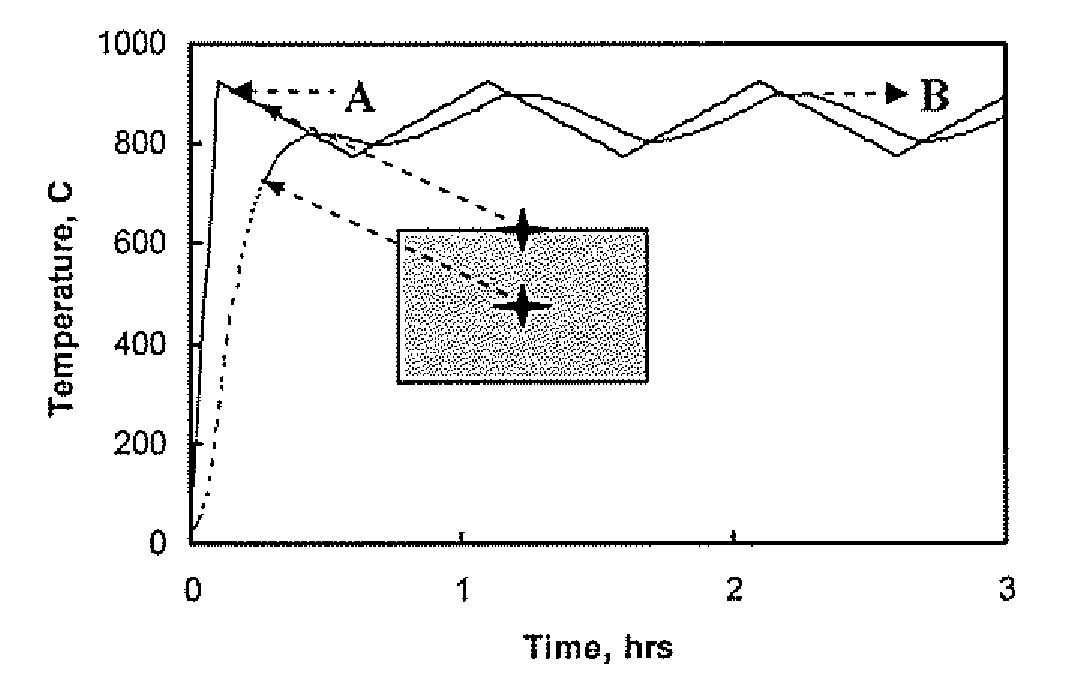
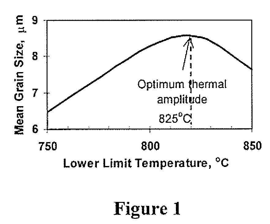
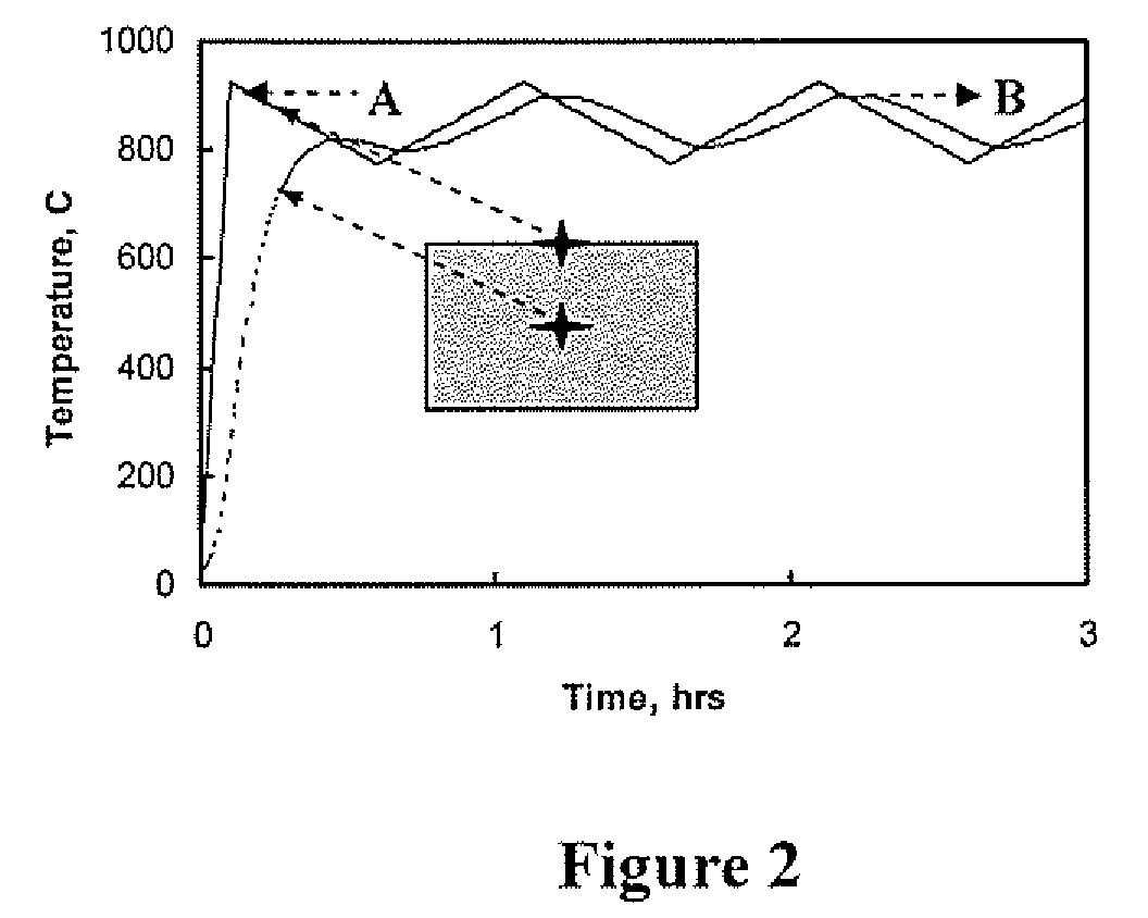
[0018]a) Samples from Ti-6A1-4V alloy rods (each of 15 mm diameter and 3 mm thickness) were subjected to cyclic thermal processing at different thermal amplitudes in a laboratory furnace. The upper temperature of the thermal amplitudes was kept constant at 925° C. and the lower temperature of the thermal amplitudes was varied from 750 to 850° C. The heating and cooling rates for all the samples were kept at 5° C. / min. The optimum thermal amplitude at which phase transformation kinetics of the samples was maximum was found to be when the samples were annealed at the thermal amplitude of 100° C. with the higher and lower temperatures at 925° C. and 825° C., respectively as illustrated in FIG. 1 of the accompanying drawings. A thermal amplitude of 150° C. higher than the optimum thermal amplitude was selected wherein the upper temperature was 925° C. and the lower temperature was 775° C. The higher thermal amplitude was selected by mathematical simulation. The rods were subjected to cy...


PUM

PropertyMeasurementUnit
temperatureaaaaaaaaaa
temperaturesaaaaaaaaaa

Abstract

A method of thermal treatment of components. The optimum thermal amplitude of the components at which the phase transformation kinetics of the components is maximum is determined by subjecting samples of the components to cyclic thermal processing at various thermal amplitudes by maintaining the upper temperature constant and varying the lower temperature. A thermal amplitude which is higher than the optimum thermal amplitude is selected. The components are subjected to cyclic thermal processing at the thermal amplitude selected above to achieve near uniform phase transformation kinetics of the components across their crosssection. The components are cooled down to room temperature to obtain components with near uniform microstructure and properties.

Description

FIELD OF INVENTION[0001]This invention relates to a method of thermal treatment of components.[0002]The term “components” as used in the specification includes parts which are fabricated, shaped, formed or cast with materials or compacted with powder. Examples of the components include bearings, wheels, sprockets, gears, shafts, wires or rods used in various industries including automotive, aerospace or electrical and electronic industries.BACKGROUND OF INVENTION[0003]Components are subjected to thermal treatment to bring about changes in their microstructure and to develop various properties such as hardness, ductility or tensile strength so as to obtain the desired performance of the components. Thermal treatment is generally carried out by isothermal processing or cyclic thermal processing. Isothermal or cyclic thermal processing comprises isothermal or cyclic annealing, age hardening or sintering. During isothermal thermal processing, depending upon the material and nature of th...

Claims


Application Information

Patent Timeline
Patent Type & Authority Patents(United States)
IPC IPC(8): H05B1/02
CPCC22F1/183C22F1/00
Inventor SAHAY, SATYAM SURAJKRISHNAN, KARTHIK
Owner TATA CONSULTANCY SERVICES LTD
Why Eureka
Try Eureka