Adsorption, detection and identification of components of ambient air with desorption/ionization on silicon mass spectrometry (DIOS-MS)

a technology of silicon mass spectrometry and component detection, applied in the direction of optical radiation measurement, isotope separation, particle separator tube, etc., can solve the problems of inability to quantitatively measure colorimetric indicators, limited instrument sensitivity, and inability to detect components of gas low concentration, so as to avoid thermal degradation of components

Inactive Publication Date: 2009-07-21
WATERS TECH CORP
View PDF24 Cites 40 Cited by
  • Summary
  • Abstract
  • Description
  • Claims
  • Application Information

AI Technical Summary

Benefits of technology

[0017]Because the process of laser desorption / ionization and mass detection of the components from the porous silicon surface does not require the elevated temperatures of prior art systems, thermal degradation of the components is avoided. Thus, the invention provides for the adsorption of components contained in a gas, for example, ambient air, without the need for applied heat that may cause thermal degradation of analytes.

Problems solved by technology

Although such calorimetric devices are usually inexpensive, they are not useful in the detection of gas components generally because they are limited by the reactivity of the solid indicator material for the complementary specific chemicals for which they were designed.
Furthermore, colorimetric indicators are generally not capable of quantitative measurement.
Frequently, the detection of low concentration components of gases is limited by the sensitivity of instruments.
Gas-liquid extraction methods are not widely used because they typically require large volumes of solvent, expensive machinery, and lengthy analysis times.
The sorbent material may be inadvertently overloaded.
If the sorbent is highly retentive of an adsorbed trace material, then it will require relatively large elution volumes.
Also, the analyte may react with the sorbent material or the material itself may cause introduction of interfering contaminants that compromise the analytical data.
There is the added disadvantage of the time required to regenerate (or replace and condition) the chemical sorbent or membrane, and carry out the gas-chromatographic separation prior to detection, which limits output.
Unless the pre-concentrator tube is heated for a sufficiently long time, all of the accumulated analytes may not be released, and the sample of chemical released from the sorbent material that reaches the detector may not accurately reflect the concentration of chemical entering the sorbent material.
In order to measure analytes present in concentrations below about 1 ppb in air, a relatively large volume of sorbent, which requires large elution volumes, may be required, and in such cases some substances (particularly non-volatile trace materials) that bind very strongly may be difficult to desorb.
As a practical matter, cryogenic methods of pre-concentration are limited by small sample volumes (about 10 mL or less).
Also, the use of thermal focusing with a gas chromatography system produces undesirable dead volume and band broadening which adversely affect system resolution and efficiency.
The requirement of application of heat in both sorbent-based pre-concentration methods and thermal focusing methods is a significant limitation.
Therefore, these methods are not ideally used in the analysis of thermal sensitive compounds.
In GC thermal focusing, analytes may be exposed to excessive temperatures in order to volatilize them entirely through the focusing chamber, thereby causing thermal decomposition.
Instead of actual analytes of the original sample being ejected from the column, these components become fragmented, which significantly complicates analysis.
Furthermore, the entire length of the cold trap sample tube cannot be maintained ideally at a uniform constant temperature, either during the collection or injection modes, and a thermal gradient exists.

Method used


Image

  • Adsorption, detection and identification of components of ambient air with desorption/ionization on silicon mass spectrometry (DIOS-MS)
  • Adsorption, detection and identification of components of ambient air with desorption/ionization on silicon mass spectrometry (DIOS-MS)
  • Adsorption, detection and identification of components of ambient air with desorption/ionization on silicon mass spectrometry (DIOS-MS)

Examples


examples

[0133]The invention is further illustrated by the following example, which should not be construed as further limiting.

Detection of Nicotine in Cigarette Smoke

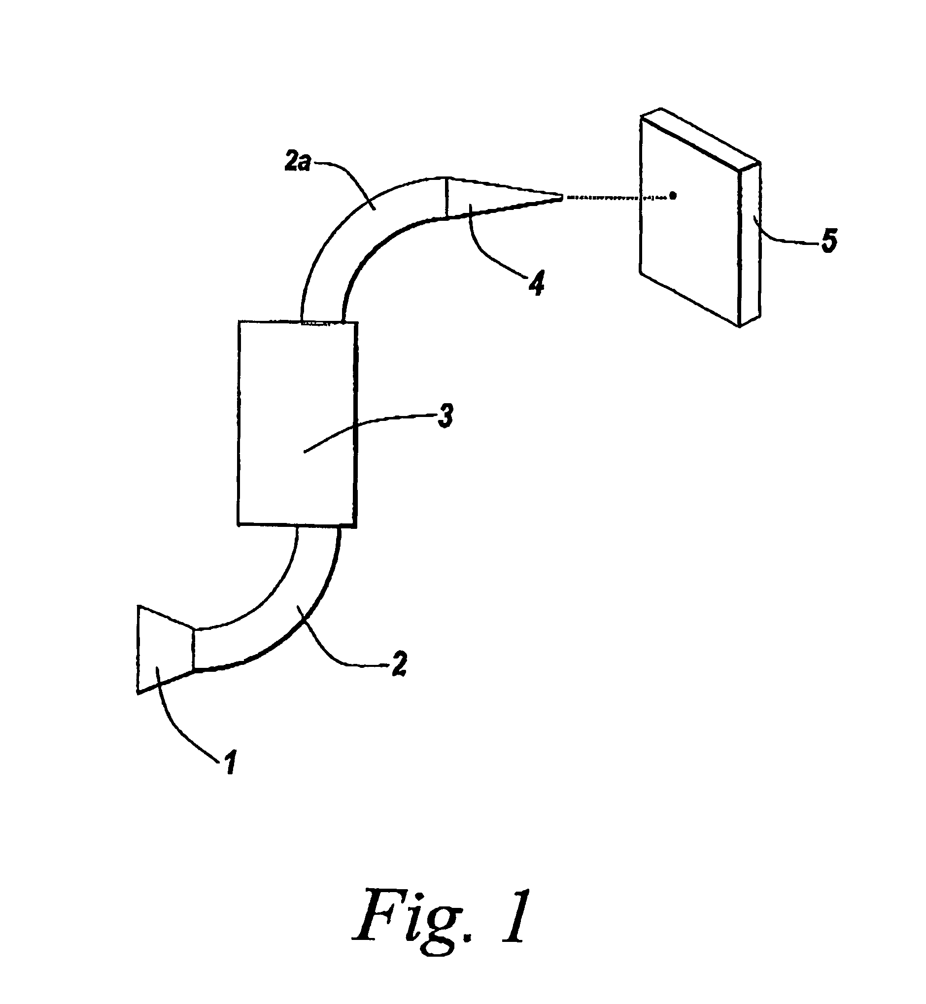
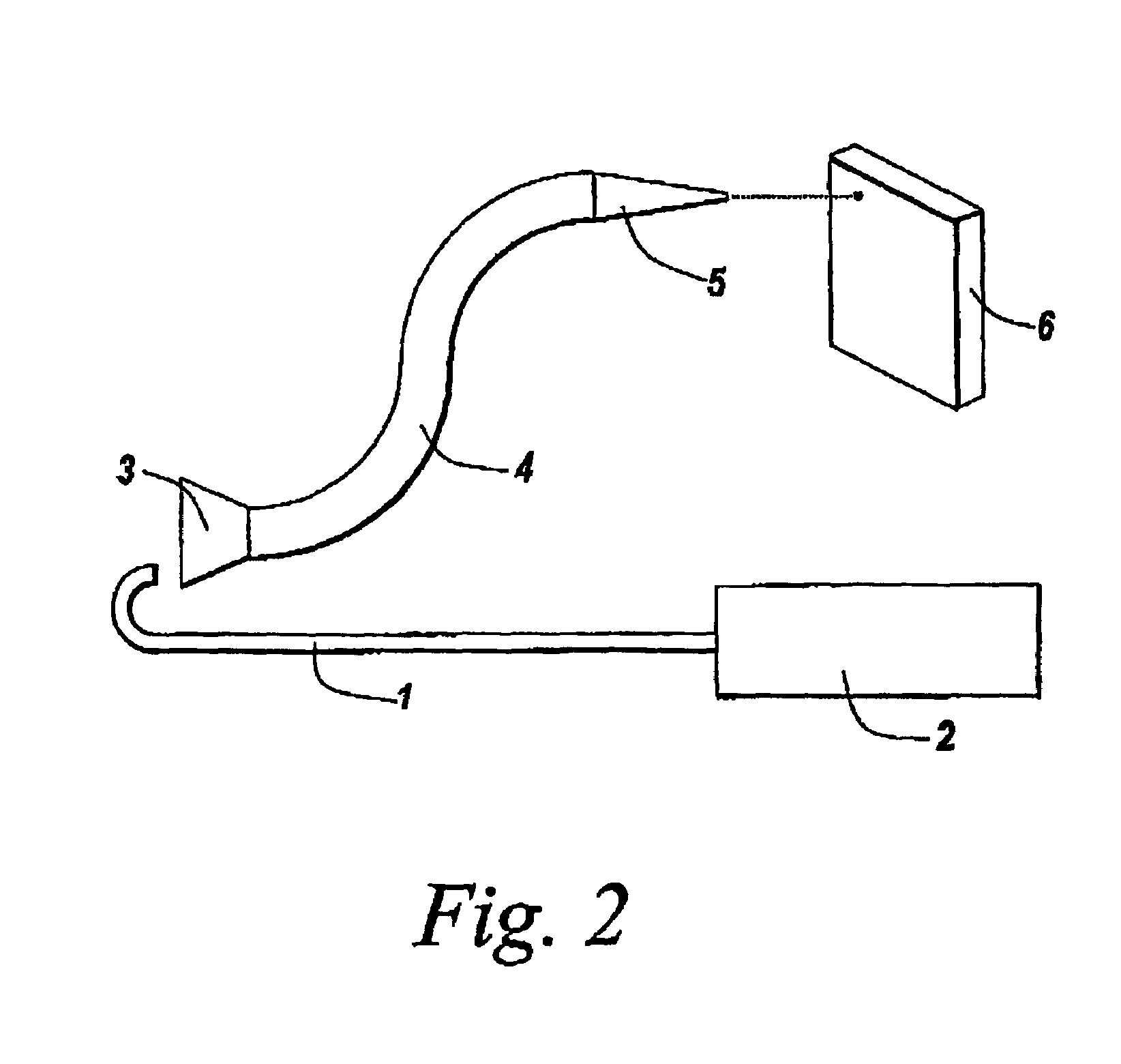
[0134]A lit cigarette was mounted in a glass holder (a short segment of glass cut from a disposable pipette) and connected to the side-arm of an Erlenmeyer flask by inert plastic tubing. The mouth of the flask was fitted with a rubber stopper through which a glass disposable pipette was inserted. The end of the pipette projecting out of the flask was connected to a diaphragm pump, thereby forming a closed system extending from the burning cigarette, through the chamber of the flask, and finally to the pump. The pump was engaged in order to draw smoke from the cigarette into the chamber. When sufficient smoke had been collected, the pump was disengaged and replaced with a source of compressed air, and the cigarette and the holder were replaced with a glass disposable pipette. Gas flow through the system was reversed and the tra...


PUM

PropertyMeasurementUnit
porosityaaaaaaaaaa
porosityaaaaaaaaaa
positive voltageaaaaaaaaaa

Abstract

The present invention provides a device, system, and associated methods to actively or passively sample air by directing it onto the surface of a porous light-absorbing semiconductor, for example, a desorption / ionization on porous silicon (“DIOS”) chip. Upon adsorption of an analyte, the surface may be analyzed directly by laser desorption / ionization time-of-flight mass spectrometry. Because the process of laser desorption / ionization and subsequent mass detection does not require elevated temperatures, thermal degradation of analytes is avoided.

Description

RELATED APPLICATIONS[0001]This application is a U.S. national phase application, pursuant to 35 U.S.C. §371, of PCT international application Ser. No. PCT / US2004 / 003719 filed Feb. 9, 2004, designating the United States, which claims priority under 35 U.S.C. §119 to U.S. provisional patent application Ser. No. 60 / 446,383 filed Feb. 10, 2003, U.S. provisional patent application Ser. No. 60 / 446,453 filed Feb. 10, 2003 and U.S. provisional patent application Ser. No. 60 / 474,457 filed May 30, 2003. The entire contents of the aforementioned patent applications are incorporated herein by this reference.BACKGROUND[0002]The measurement and detection of components of gases, particularly ambient air, are important in environmental monitoring, forensics, and as a research tool.[0003]In one simple technique, a colorimetric indicator containing a specific solid that absorbs components from a gas and reacts with it, qualitatively detects the presence of certain analytes by producing a characterist...

Claims


Application Information

Patent Timeline
Patent Type & Authority Patents(United States)
IPC IPC(8): H01J49/00G01D
CPCG01N1/2214H01J49/0418H01J49/0422Y10T436/24Y10T428/24802Y10T428/2913Y10T436/25Y10T428/29Y10T428/249953G01N30/00H01J49/161
Inventor FINCH, JEFFREY W.STUMPF, CHRIS L.COMPTON, BRUCE J.
Owner WATERS TECH CORP
Why Eureka
Try Eureka