
Method and apparatus of lining pipes with environmentally compatible impervious membrane

a technology of impervious membrane and lining pipe, which is applied in mechanical equipment, lighting and heating apparatus, coatings, etc., can solve the problems of unsuitability, unsuitability for many applications, so as to avoid slumps and fast reaction

Active Publication Date: 2009-09-22
NEUBAUER KURT +1
View PDF5 Cites 31 Cited by
  • Summary
  • Abstract
  • Description
  • Claims
  • Application Information

AI Technical Summary

Benefits of technology

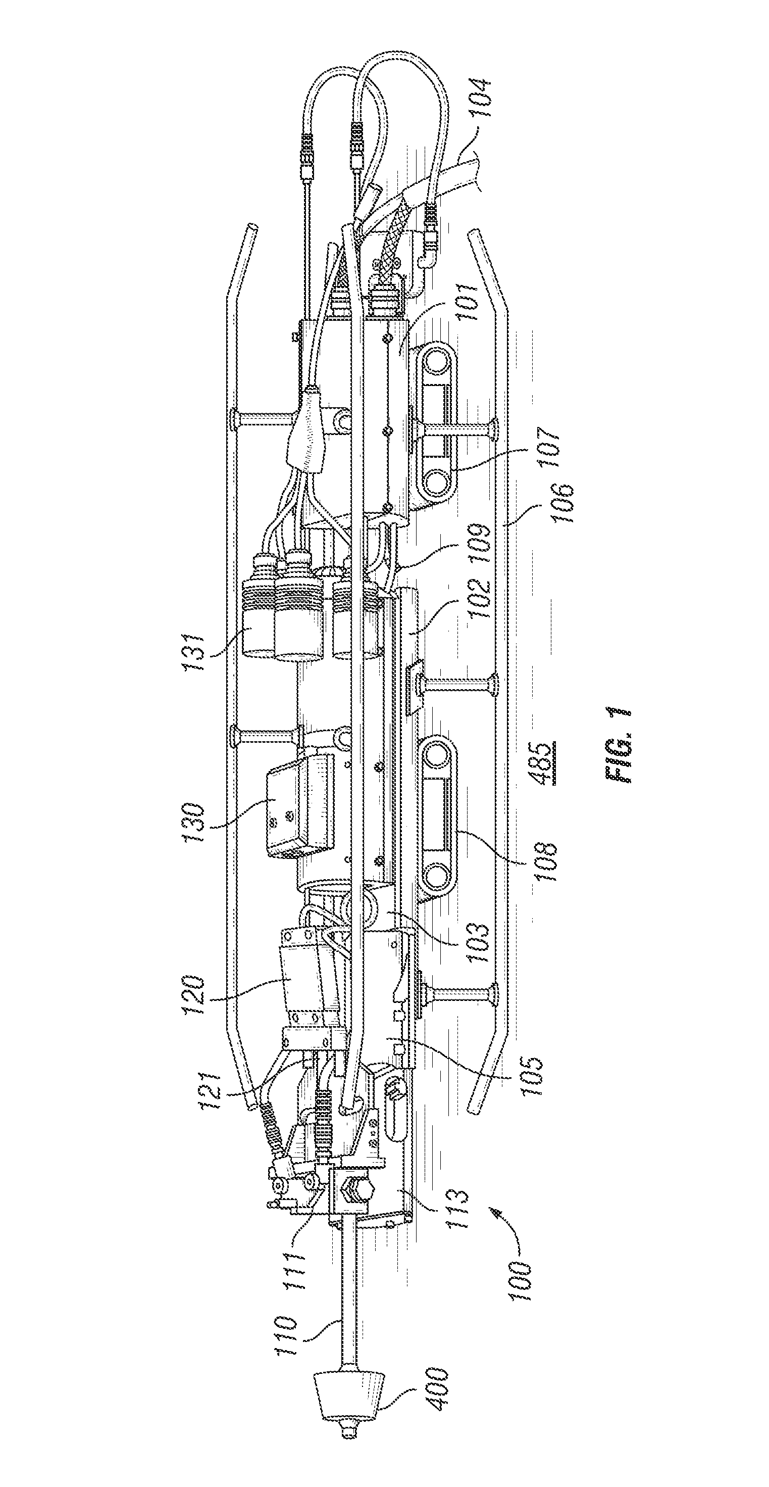
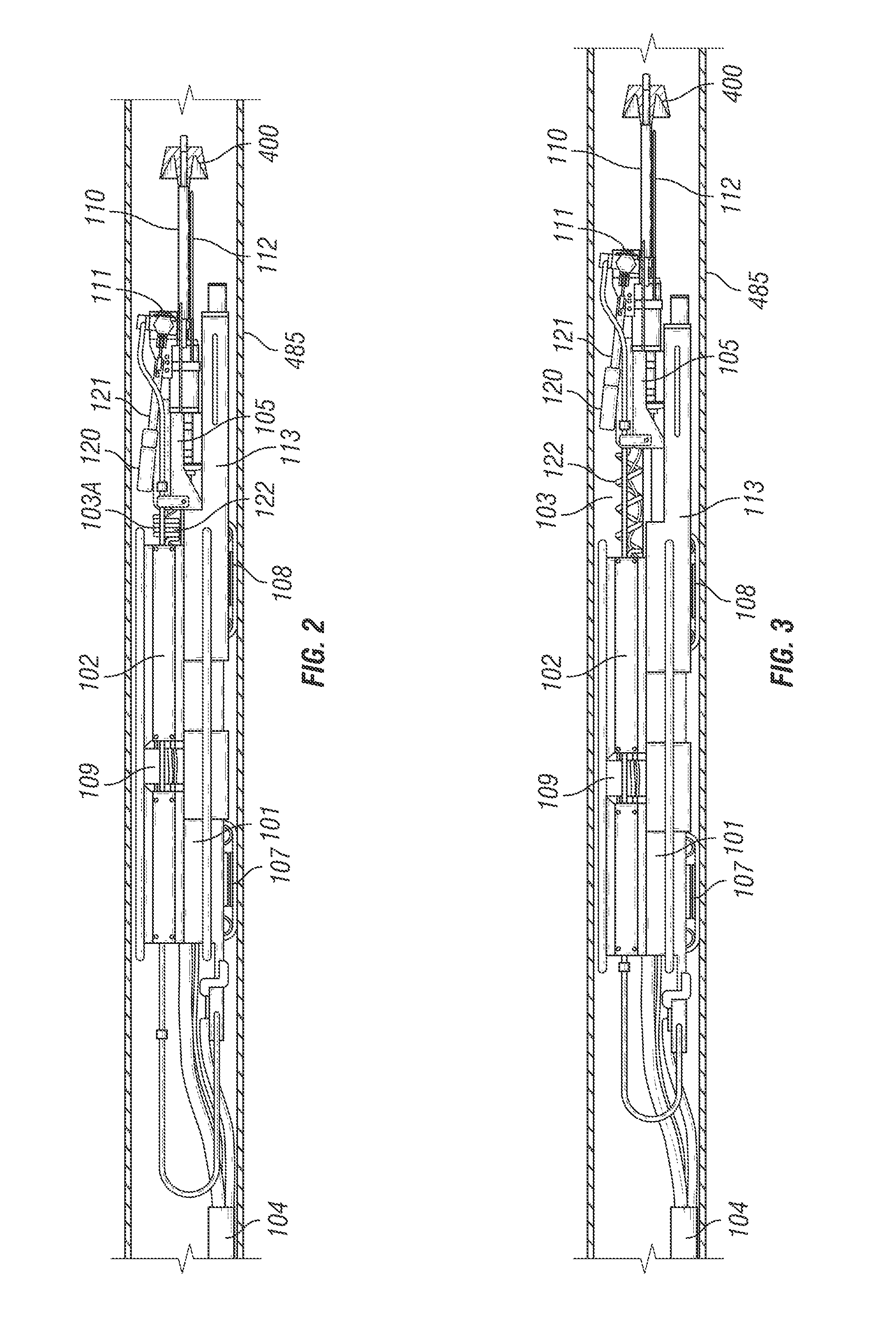
[0069]This disclosure teaches a method and apparatus that allows remote installation of liners inside pipes for distances exceeding 1,000 linear feet with only one insertion and one extraction of the apparatus. In one embodiment, the liner is a reaction product of isocyanate and amine resin mixed in situ at high temperature and pressure immediately prior to spraying the liner on the pipe wall. In one embodiment, the temperature may be within the range of 140° F. to 170° F. with the ideal temperature of 155° F. The pressure of the liquid components may be between 1700 psi to 3500 psi depending upon the viscosities of the materials and the necessity for molecular cross linking. The cured liner is inert and free of VOC's, carbon fluorocarbons and endocrine disrupters. The cured liner is impervious to influent and effluent. Therefore a liner installed with the apparatus of the invention and the method disclosed herein will stop effluent from entering the ground and ground water.
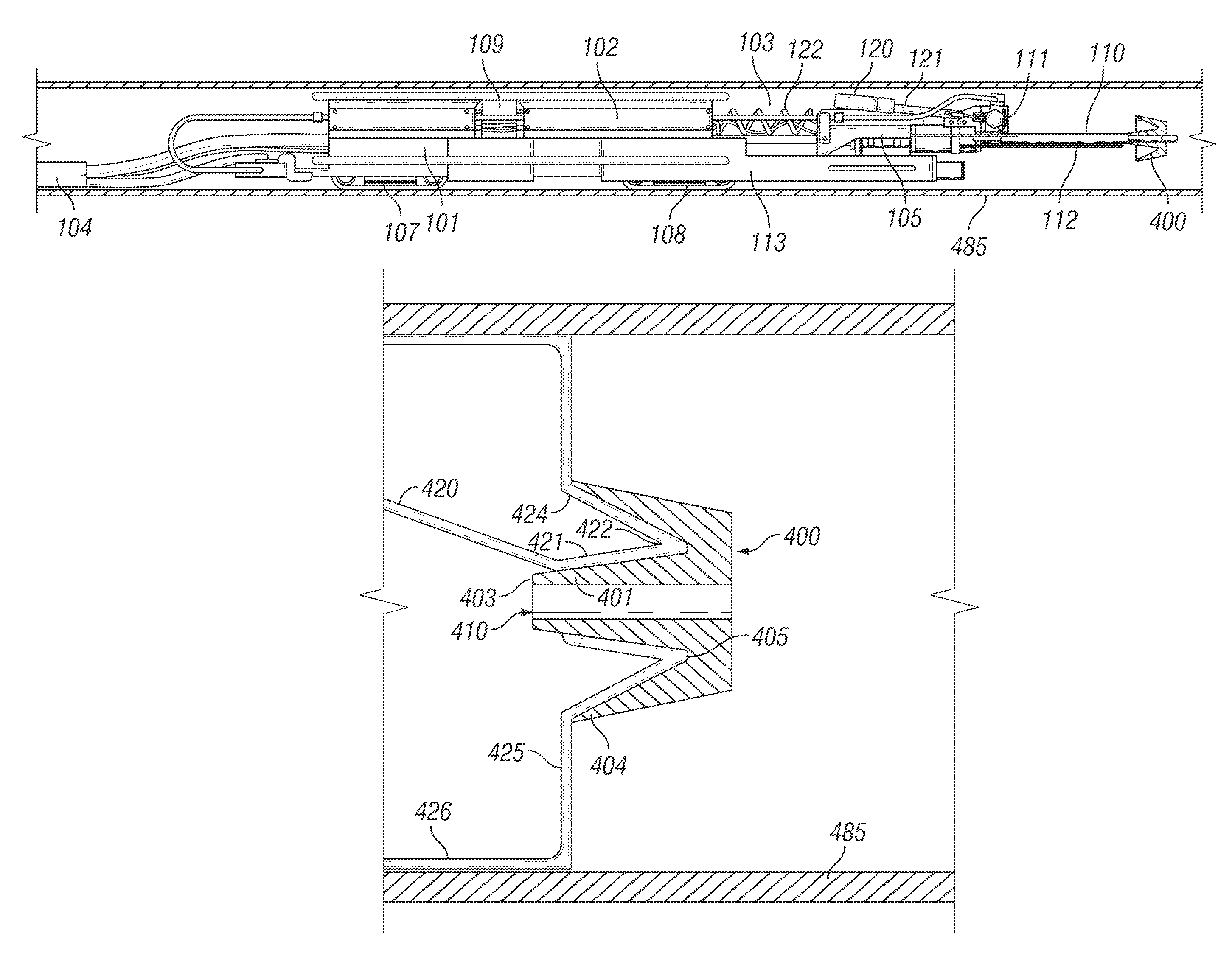
[0110]Continuing, the angle of trajectory of the liquid liner causes it to stream onto the interior acutely angled side of the rotating dissipation device. This is proximate to the center top of the device. The liner strikes the dissipation device at between 1700 to 3,500 psi dependant on material viscosities. The dissipation device is shaped like a letter “W”. The middle portion is designated the center top. The inside portion of the bottom of the W is the pocket segment of the dissipation device wherein the liquid liner can briefly dwell and equalize its mass before being pulled over the outer flange by the operation of centrifugal force. Due to the rapid rotation of the dissipation device, the curing liquid liner sprayed from the device evenly lines the interior pipe in a 360 degree circumference.

Problems solved by technology

There are many instances and conditions where the above methods are either not practical or are unsuitable.
A seamed monolithic liner is created by the inability of the lining method or apparatus to continuously line a section of pipe.
As a result there are stop points in the lining and replacement lining overlaps the previously applied liner, thereby causing a seam.
Typical, prior art spray in type liners experience major problems as evidenced in the plugging of spray tips, slow curing coatings resulting in surface sags and inconsistent material application thickness and other constraints resulting in finished liner thicknesses in the 0.200-0.400 inch range, rendering them unsuitable for many applications.
The combination of these two assumed improvements actually result in a compounded problem.
Unfortunately adding air flow to the product stream only increases the atomization of the spray resulting in higher static attraction to moving parts.
Purging the spray tip with compressed air does not eliminate the plugging problem.
This flat or slightly obliquely angled spinning disc design as it relates to the direct right angle diffusion of the spray causes a significant amount of rebounding / ricochet lining material to accumulate on the splatter shield and air blow off mechanism, ultimately resulting in total blockage of the tip and other crucial mechanical functions within a short period of time.
This does not allow for continuous operation or lining of more than 10-20 feet of pipe without the need to retract the apparatus and clean.
The spinning disc design of Davis fails to satisfy the requirement for a uniform lining thickness as well.
As described, the resultant physics do not afford equal dissipation of lining material in the full 360 degrees of circumference.
The current apparatus due to its flat or slightly oblique design does not afford the coating material any dwell time to equalize mass and distribute the coating material around the circumference of the disc prior to being ejected.
This presents an unacceptable condition when uniformity is necessary to calculate ultimate liner properties and performance which is required by end users.
Forced air is not a cure for static build up.
These formations will in time severely impede if not halt the apparatus' ability to continually line the pipe.
The build up of these formations will divert the flow from the tip to the spinner disc resulting in additional disproportionate distribution of coating material to the pipe wall.
Formations that get imbedded in the uncured liner causing profiles in the flow channel that will result in diminished flow capacity of the liner due to increased coefficient of friction.
Also the imbedded pieces causes “snag” areas in mixed effluent pipelines such as sewage which results in solids—toilet paper etc—getting caught on them and building up sometimes to block pipeline flow.
This creates through voids in the finished liner.
This situation results in the need to remove the prior art apparatus from the pipe and clean many times to actually complete a full liner application hence diminishing the claims of a faster method in prior art.
Current art has an inherent design that has no way of stopping the build up of coating material on the spinner disc.
This does not allow the disc to totally disperse the lining material as the material does not have the weight and mass needed to completely propel off the disc effectively.
The initial required rpm is then never fully achieved.
The pneumatic motor produces high rpm's and low torque.
Hydraulic units work but the need to supply hydraulic pressure at 500 feet requires bulking up the umbilical with hoses, adding costly pumps and additional weight and diameter to the umbilical.
The above mentioned “dry fall” effect starts to gradually slow the rpm of the spinner disc due to the weight of the resulting build up.
As the rpm slows due to low torque, the effect becomes greater and greater having a “snowball” effect on the apparatus, completely stopping the spinner disc and ultimately rendering the apparatus incapacitated in as little as 10 minutes.
This results in the need to constantly remove the apparatus from the pipe and clean the shaft and disc which can take hours then reinserting to once again line for a short amount of time.
This consistent required retraction and insertion can result in inter-coat de-lamination of the liner due to possible contamination of the already installed liner while the retraction process and cleaning process is being completed.
This, however, is not possible in a single insertion and retraction cycle.
This adds considerable time to the process evacuating any advantage in time or economics over other lining methods as stated in prior art.
This design results in a straight stream of dissipation off the spinner disc.
The prior art does not have the ability due to its design, mechanics and straight or right angle stream to completely line the forward or backward edge of these profiles as it relates to the position of the apparatus.
Prior art also does not have the ability to reverse the rotation on the spinner disc.
In this instance there is no way that lining can be placed on the underside of this intrusion pipe or any profile for that matter without counter rotation.
The reason for this is that on high rpm air motors they easily wear out if they are run in both directions.
Compounding this problem in the prior art is that the unit does not have the ability to start and stop flow.
Prior art design and mechanics do not allow to open and close the valving rod or spray tip stopper more than one open and close cycle.
The prior art mechanics does not have the pull force or the ability to have a momentum surge on the valving rod to break this free—hence the valving rod cannot be remotely opened up more than one cycle—open / close—done.
If not the result is heavy rings in the liner.
This is a very time consuming process.
This design and mechanical flaw also does not allow the apparatus to complete sleeve or individual repairs in the pipe unless you do them one at a time due to the necessity to clean after every valving rod cycle.
Equipment of the prior art, due to its overall length, cannot be inserted or retracted from an underground pipe with the access being a manhole or vault with a diameter or horizontal dimension or less than 5 feet.
This is a very time consuming process.
This, however, does not afford this apparatus the ability to coat the entire pipe.
There is currently no acceptable way afterward to line this section that is void of lining material.
There is no way after this in a small diameter pipe to get in and manually line the pipe section that was missed.
Due to the design and mechanics of the prior art, it cannot be utilized in a pipe with a diameter of less than 10″.
The basic dimensions however do not allow for this as filed in the drawings.
Over and above the fact that the unit's dimensions restrict its ability to line pipe with diameters less than 10″, its function of mechanics also severally impedes this ability.
This results in all oscillating parts to be on the exterior of the apparatus and in close proximity to the pipe wall.
In either case it causes a build up or “ringing” in the new coating which is unacceptable.
This exposes them to all the overspray and existing contaminants that are in the pipe while being coated.
This eventually impedes their function resulting in diminished capabilities or incapacitation.

Method used


Image

  • Method and apparatus of lining pipes with environmentally compatible impervious membrane
  • Method and apparatus of lining pipes with environmentally compatible impervious membrane
  • Method and apparatus of lining pipes with environmentally compatible impervious membrane

Examples


Embodiment Construction

[0069]This disclosure teaches a method and apparatus that allows remote installation of liners inside pipes for distances exceeding 1,000 linear feet with only one insertion and one extraction of the apparatus. In one embodiment, the liner is a reaction product of isocyanate and amine resin mixed in situ at high temperature and pressure immediately prior to spraying the liner on the pipe wall. In one embodiment, the temperature may be within the range of 140° F. to 170° F. with the ideal temperature of 155° F. The pressure of the liquid components may be between 1700 psi to 3500 psi depending upon the viscosities of the materials and the necessity for molecular cross linking. The cured liner is inert and free of VOC's, carbon fluorocarbons and endocrine disrupters. The cured liner is impervious to influent and effluent. Therefore a liner installed with the apparatus of the invention and the method disclosed herein will stop effluent from entering the ground and ground water.

[0070]Th...


PUM

PropertyMeasurementUnit
Timeaaaaaaaaaa
Pressureaaaaaaaaaa
Lengthaaaaaaaaaa

Abstract

A method and apparatus for remotely installing a monolithic liner in a conduit is disclosed. The apparatus includes a main component body including electromagnetic actuators, pneumatic cylinders, linear actuators relays, solenoids, ion generator, attachment points for tethers, umbilical, cameras and diameter specific guides and a reciprocation head attached thereto. The longitudinally traversing reciprocation head incorporates a fluid driven rotary turbine motor assembly communicating with shaft and self cleaning dissipation device integrating both conical and inverted cone surfaces. Also included on the reciprocating assembly is an impingement block for the efficient mixing of products and a termination mechanism for the precise remote control of product flow. Additionally, the assembly provides the ion generator to direct a stream of negatively charged air flow to the shaft and the diffusion device to effectively prohibit excess material accumulation.

Description

BACKGROUND OF INVENTION[0001]1. Field of the Invention[0002]With general infrastructure within the US and around the world in a precarious state of decay it has been the object of many to provide for a cost effective method to perform in situ-rehabilitation of these properties. In the industrial sector, pipe and transmission lines carrying volatile and dangerous or hazardous materials are constantly at risk of failure due to age, neglect or lack of funds to replace or repair with traditional methods. In the global municipal arena, waste collection and water distribution systems are seriously compromised with failures creating community disturbances, commercial loss and environmental incidents. The US EPA Clean Water Act of 1989 outlines mandatory restrictions and covenants imposed on municipalities to improve the conditions of their water and wastewater systems. The EPA Conference of Mayors report of 2007 surveyed 1500 US Cities' infrastructure needs resulting in $15B in needed repa...

Claims


Application Information

Patent Timeline
IPC IPC(8): B05B13/06B05B3/00B05B3/10
CPCB05B13/0636F16L58/1027F16L55/18F16L55/26F16L55/1645B05B3/001B05B3/1014B05D7/22B29C63/26B29C63/34
Inventor WEISENBERG, KENT
Owner NEUBAUER KURT
Learn More