Method and device for changing light in an adjustable manner

a technology of adjustable light and light, applied in the field of microscopy, can solve the problems of poor efficiency of separation of excitation light from emitted light, affecting the optical resolution of the arrangement, and reducing the efficiency of detection

Inactive Publication Date: 2009-10-20
CARL ZEISS MICROSCOPY GMBH
View PDF20 Cites 14 Cited by
  • Summary
  • Abstract
  • Description
  • Claims
  • Application Information

AI Technical Summary

Problems solved by technology

Hence, the use of dichroic beam splitters, according to the prior art, results in poor efficiency of the separation of the excitation light from the emitted light.
The drawback with the methods for dividing the numerical aperture, known from the prior art (e.g. EP 1353209), is that, on the one hand, the efficiency of detection and, on the other hand, the optical resolution of the arrangement decreases due to the restriction of the aperture.
The drawback with all of the methods, according to the prior art, is that the separation of the excitation light from the light, emitted by the specimen, is carried out in a wavelength-dependent manner, i.e. not flexibly adjustable, or with a limited efficiency of typically 70% to 90%, depending on the required spectral characteristics and the quantity of illumination lines.
If this is not guaranteed, then the result is a reduction in the detection efficiency, particularly in the case of a confocal detection, and/or aliasing errors, because when different wavelengths are

Method used


Image

  • Method and device for changing light in an adjustable manner
  • Method and device for changing light in an adjustable manner
  • Method and device for changing light in an adjustable manner

Examples


Embodiment Construction

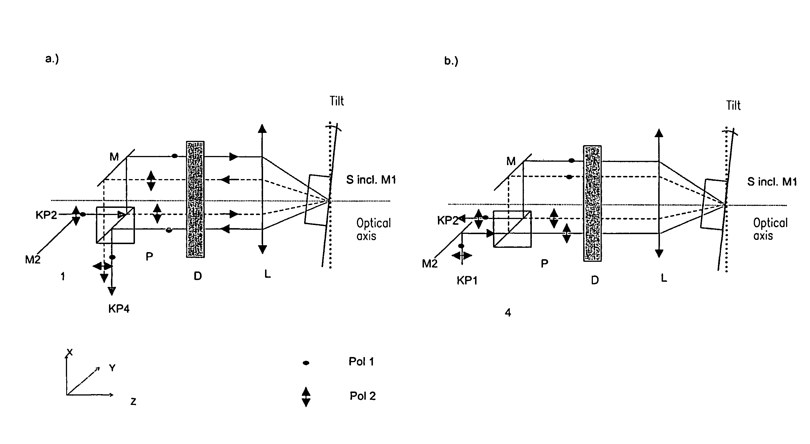
[0052]FIG. 4 shows the inventive arrangement in reflection.

[0053]In FIG. 4a, an essentially unpolarized light from the specimen reaches a polarizing beam splitter P by way of a coupling port KP 2, is split by this polarizing beam splitter into perpendicular polarization components (arrows or dots). In this respect, one component reaches directly a dispersive element D; and the other component is mirrored at the splitter P and reaches the element D by way of a mirror M and is split spectrally at said element.

[0054]The radiation is focused on the SLM S and the mirror M1 in the plane S / M1 by means of a lens L; and, thus, its polarization can be affected in a number of ways as a function of the wavelength. Hence, the polarization of the individual spectral components of the light, which arrive again in the direction of the polarizing beam splitter P, can be varied. The SLM can comprise actively controlled liquid crystal cells.

[0055]In the plane of the SLM S, the polarization of the indi...


PUM


Abstract

Method and device for changing the illumination light and/or specimen light with respect to its spectral composition and/or intensity in an adjustable manner, wherein a spatial separation into the radiation components of different polarization is carried out with the first polarization means (Pol 1), a spectral spatial splitting of at least one radiation component is carried out with the first dispersion means (Disp1), and the polarization state of at least one part of the spectrally spatially split radiation component is changed, wherein a reflection of the illumination light and/or the detection light is carried out.

Description

BACKGROUND OF THE INVENTION[0001]1. Field of the Invention[0002]The invention relates to a method and arrangements in microscopy, in particular fluorescence microscopy, laser scanning microscopy, fluorescence correlation spectroscopy and near-field scanning microscopy, for examining predominantly biological specimens, preparations and related components. This includes methods for screening active ingredients based on fluorescence detection (high throughput screening) as well as methods of flow cytometry. Therefore, simultaneous examinations of specimens with multiple fluorophores in real time by means of simultaneous illumination of the specimen at multiple sampling points are possible with overlapping fluorescence spectra even in three dimensional structures of thick specimens.[0003]2. Related Art[0004]A typical field of application of light microscopy for examining biological preparations is fluorescence microscopy (literature: Pawley, Handbook of Biological Confocal Microscopy, P...

Claims


Application Information

Patent Timeline
IPC IPC(8): G02B21/06G01Q60/18G01Q60/20
CPCG01J3/02G02B27/283G01J3/0224G01J3/0229G01J3/14G01J3/4406G01N21/21G01N21/6458G02B21/0068G02B21/0076G02B26/0816G02B27/143G01J3/021G01N21/6445G01N2021/6417
Inventor WOLLESCHENSKY, RALFKEMPE, MICHAELKLOPFLEISCH, PETER
Owner CARL ZEISS MICROSCOPY GMBH
Why Eureka
Try Eureka