Three-dimensional joint structure measuring method

a three-dimensional joint and measurement method technology, applied in the field of three-dimensional joint structure measurement method, can solve the problems of poor repeatability, remarkable loss of structural information of joints, and inability to fundamentally solve the problem of evaluation by transmission x-ray photographs

Inactive Publication Date: 2010-02-16
TEIJIN LTD
View PDF22 Cites 14 Cited by
  • Summary
  • Abstract
  • Description
  • Claims
  • Application Information

AI Technical Summary

Benefits of technology

[0010]The above object is achieved by the following invention. That is, the present invention is able to simply and accurately extract only the 3D image of the evaluated joint on a 3D image obtained by stacking digitalized images of cross-sections of the examined joint by using a 3D image processing means. Further, the present invention is characterized by processing for filling in a joint bone medullary cavity in a joint tomographic image for extracting the morphological characteristics of the joint surface. When reconstructing a joint three-dimensionally based on the digitalized image of the examined joint tomographic image obtained by this processing and analyzing the reconstructed 3D structure, it is possible to analyze the surface structure of the joint without being affected by the inside structure of the joint, which could not be obtained with conventional 3D structural analysis, more particularly the trabecular structure inside the joint. Further, the invention is characterized by image processing for extracting a recessed region part of the joint surface, in other words, the destroyed part, from a 3D image of the joint comprised of this part and other parts by applying the method o...

Problems solved by technology

The method of evaluation using such scoring, however, suffers from various problems such as the fact that basically it is qualitative evaluation, it is greatly influenced by the degree of skill of the physician, and the repeatability is poor.
Transmission X-ray photographs, however, are transmission images from a specific direction of the examined joint and cause remarkable loss of structural information of the joints, which are originally 3D structures, more particularly the joint surface, joint destroyed part, joint space (JS), and other 3D structural information on the volume, surface area, spatial information, etc.
Further, the method of directly evaluating the destruction of the joint cartilage using MRI or ultrasonic waves in addition to transmission X-ray photographs is also being utilized, but this is basical...

Method used


Image

  • Three-dimensional joint structure measuring method
  • Three-dimensional joint structure measuring method
  • Three-dimensional joint structure measuring method

Examples


Embodiment Construction

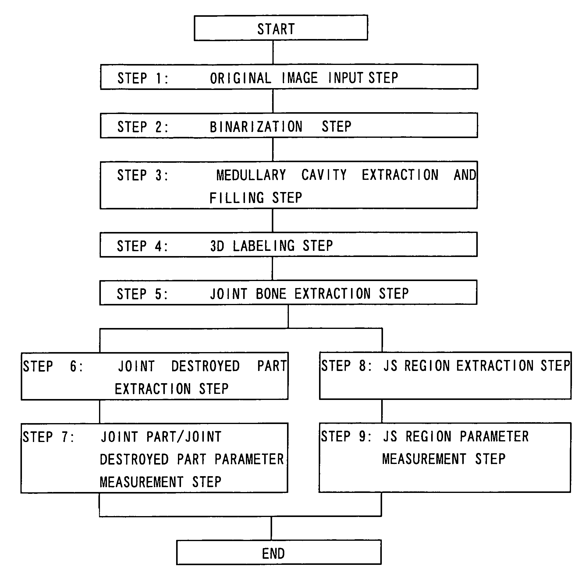
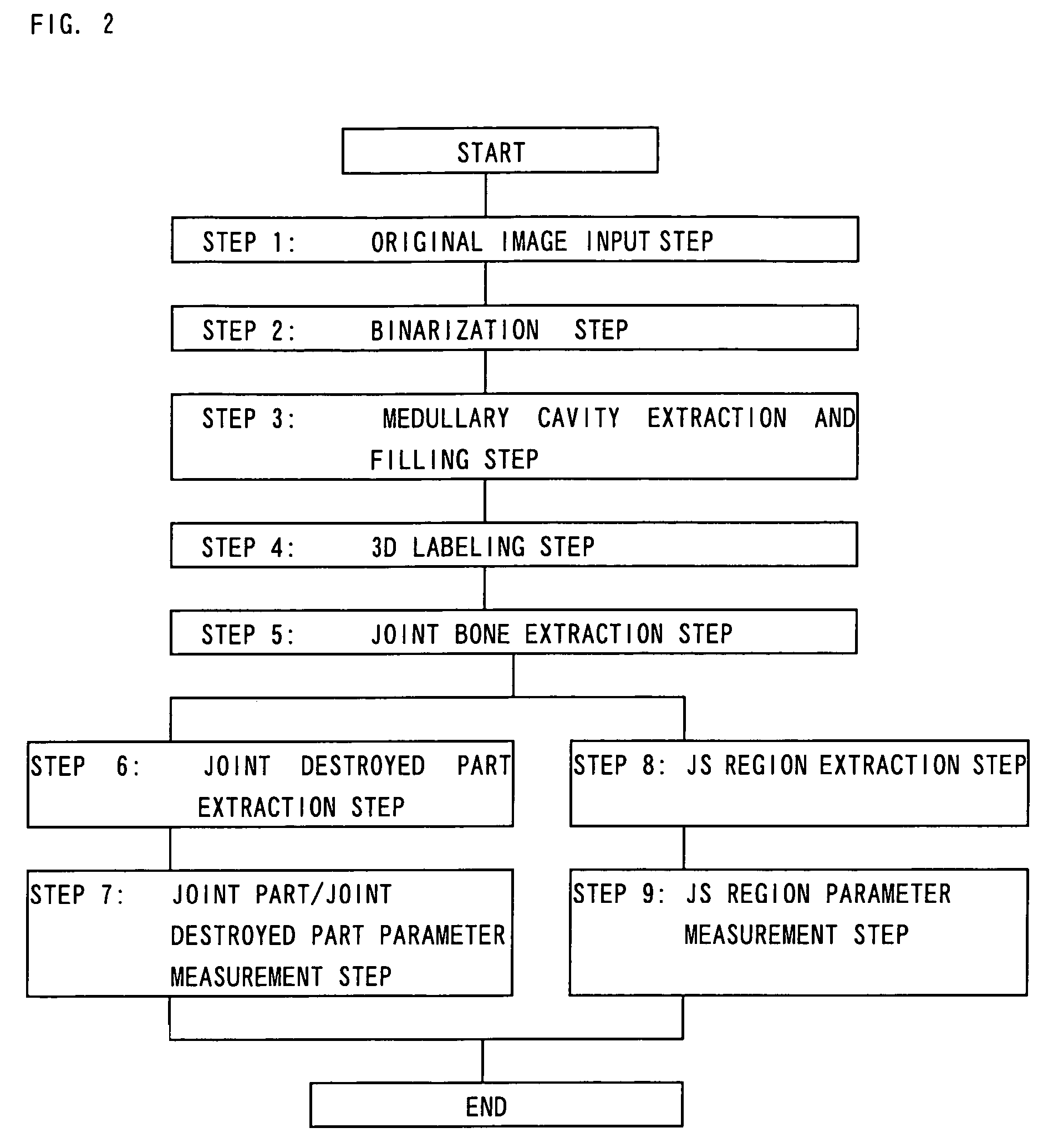
[0062]Next, examples of application to the knee joint of a rat will be explained in order along with embodiments.

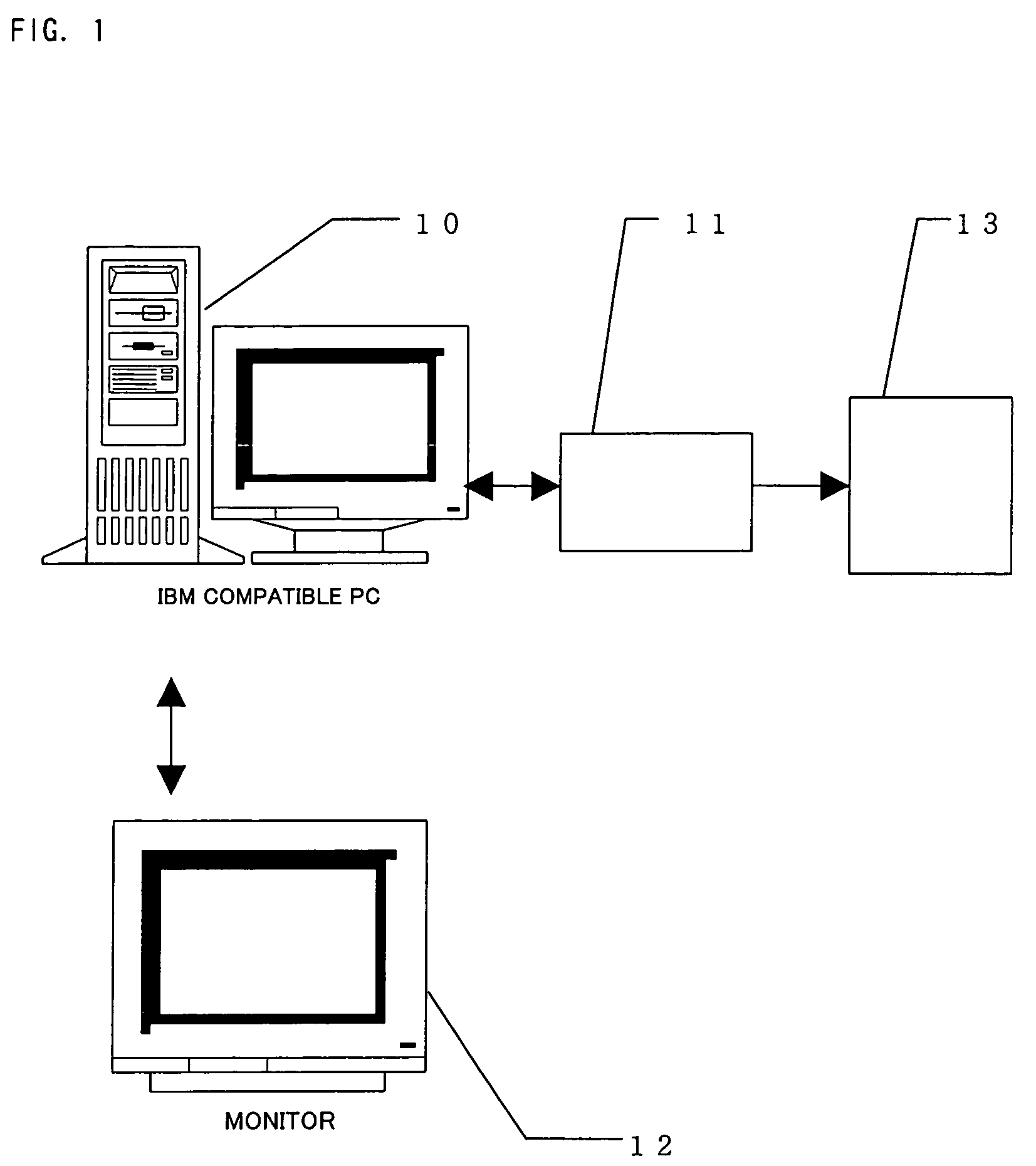
[0063]The image of the cross-section of the knee joint of a rat as the examined joint was taken using a microfocus X-ray computer tomographic apparatus (hereinafter referred to as a “μX-ray CT”) having a focal dimension and resolution sufficient for measuring the surface structure of the knee joint for the image-taking means in the present example in the same way as the method described in the specification of the above-mentioned WO 00 / 74567. Note that to obtain an image of the examined bone, it is possible to use another high resolution X-ray apparatus, magnetic resonance imaging apparatus (MRI), or apparatus for generating 2D information of the output image etc. from a film scanner or microscope.

[0064]When obtaining an image of the bone using μX-ray CT, visualization of the joint cartilage is difficult under some conditions, but evaluation of the joint subchondral bone ...


PUM


Abstract

A method enabling a destroyed part of a joint or joint cartilage to be extracted accurately and at a high speed with a good repeatability and enabling quantitative and simple 3D analysis of the joint and the destroyed part, that is, a method of 3D image processing comprising filling in a medullary cavity region, comprised of a hollow region inside a joint, of a digitalized image of a cross-section of the examined joint using the Expansion and Shrinkage method, performing 3D labeling by a 3D image obtained by stacking digitalized images of cross-sections of the examined joint generated at a step of extracting a contour of the cross-sectional image of the joint or digitalized images of cross-sections of the examined joint not pre-processed, and defining the joint image to be evaluated.

Description

FIELD OF THE INVENTION[0001]The present invention relates to a method for measuring the shape or surface structure of a joint based on a joint tomographic image, more particularly relates to a method of measurement comprising extracting a joint destroyed part (hereinafter referred to as a “destroyed part”) from a joint based on a digitalized image of the joint cross-section whereby it is possible to automatically extract a destroyed part from a joint at a high speed with a good repeatability and obtain a three-dimensional (3D) image separated into the joint and the destroyed part able to serve as the basis of nondestructive analysis of the 3D joint structure. Further, the present invention relates to a method enabling measurement of various structural parameters serving as analytical indicators such of the 3D structure etc. of the joint and destroyed part obtained by the above measurement method.TECHNICAL BACKGROUND[0002]In the past, as the method for the evaluation of a joint destr...

Claims


Application Information

Patent Timeline
IPC IPC(8): G06K9/00A61B1/32A61B6/00
CPCA61B6/505G06T7/0012A61B5/4514A61B5/4528G06T2207/30008
Inventor HARADA, YOSHIFUMIAZUMA, YOSHIAKIYAMADA, NORIHIROMAEDA, TSUTOMU
Owner TEIJIN LTD
Why Eureka
Try Eureka