Ultrasensitive biosensors

a biosensor and ultra-sensitive technology, applied in biochemistry apparatus and processes, instruments, nanoinformatics, etc., can solve the problems of large quantity of tested biochemicals required for electrophoresis detection methodologies, small number of molecules available for detection, and low sensitivity of the sensor, so as to control increase the sensitivity to the target material, and widen the effect of width

Active Publication Date: 2010-04-06
UNIV OF HAWAII
View PDF23 Cites 57 Cited by
  • Summary
  • Abstract
  • Description
  • Claims
  • Application Information

AI Technical Summary

Benefits of technology

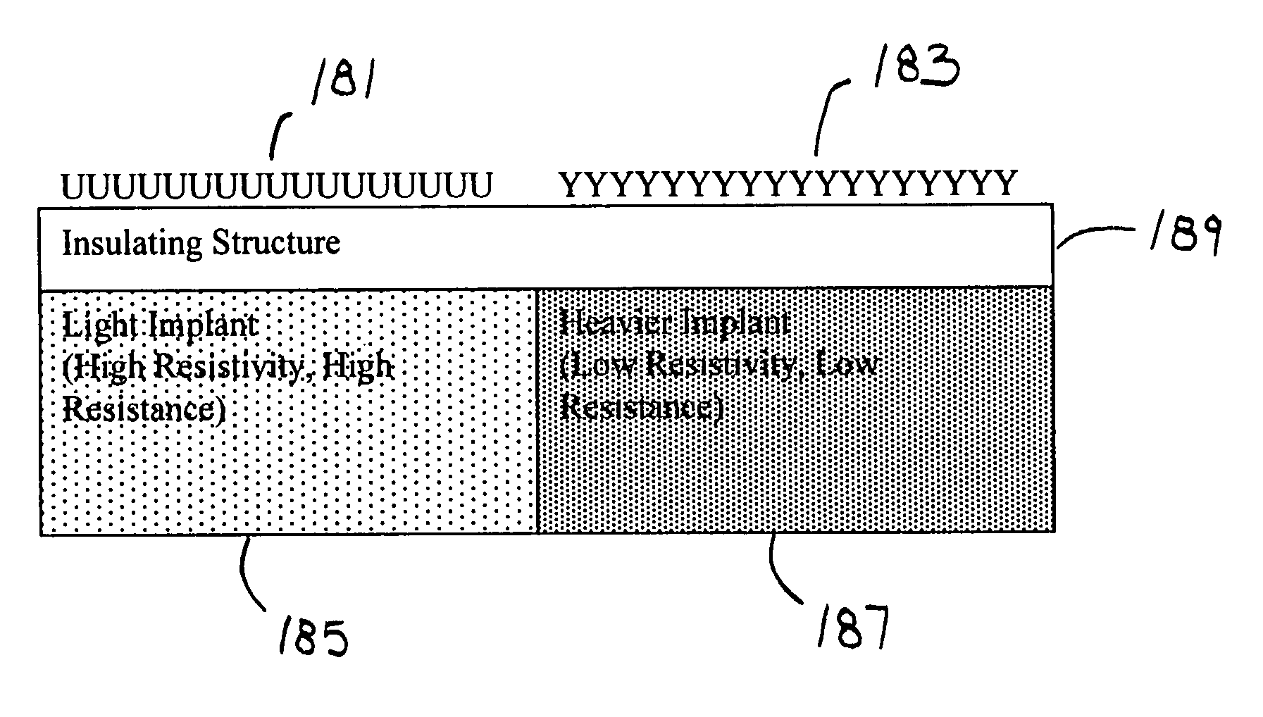
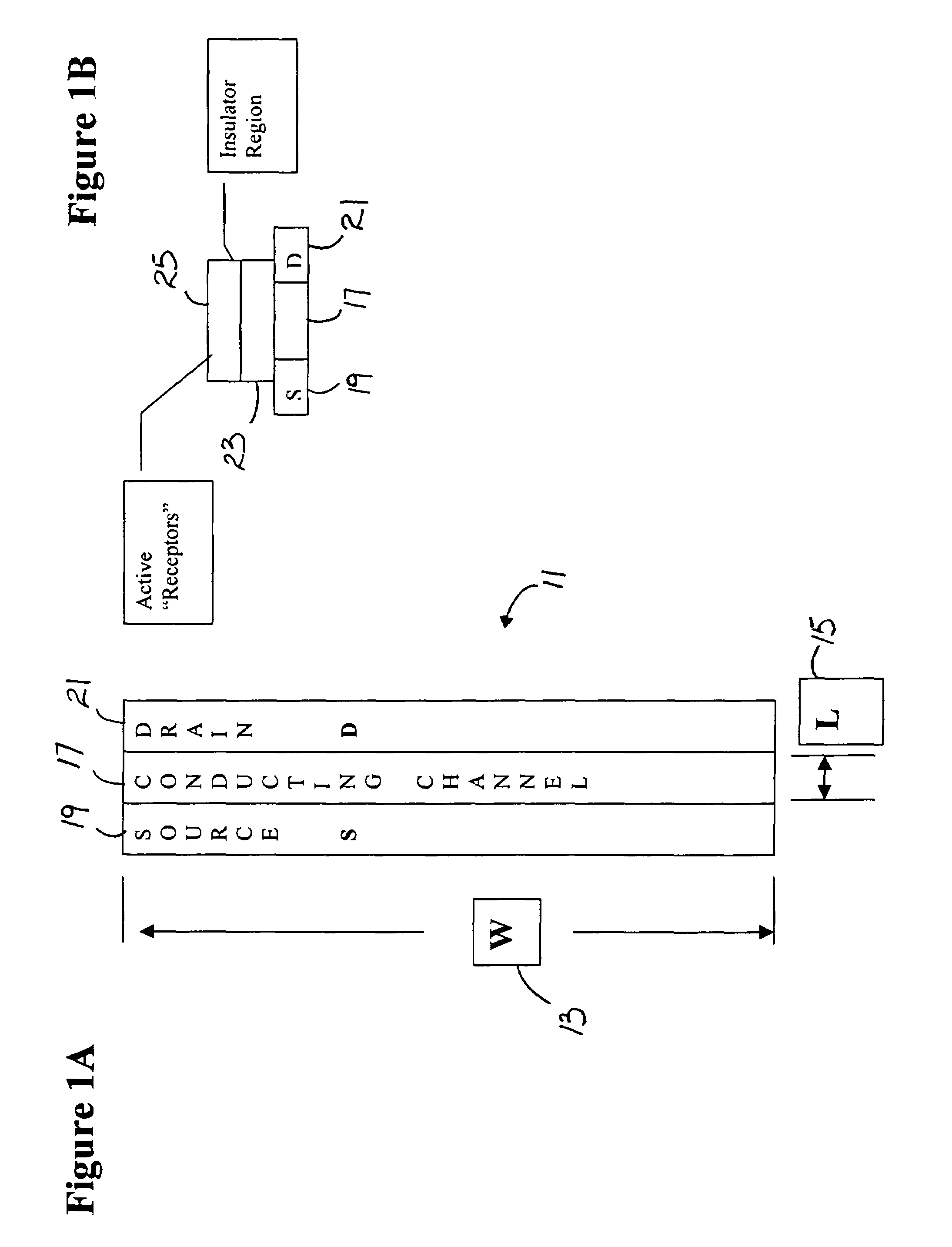
[0054]The present invention is also a method of sensing target materials including providing a substrate, providing a source in or on the substrate, providing a drain in or on the substrate spaced from the source, providing a conducting channel in or on the substrate between the source and the conducting channel, providing an insulator region on the conducting channel and on the substrate, providing a gate region on the insulator region, and providing receptors on the gate region and controlling relative widths and lengths of the source, the drain, the conducting channel, the insulator region and the gate region and thereby controlling sensitivity to the target materials.
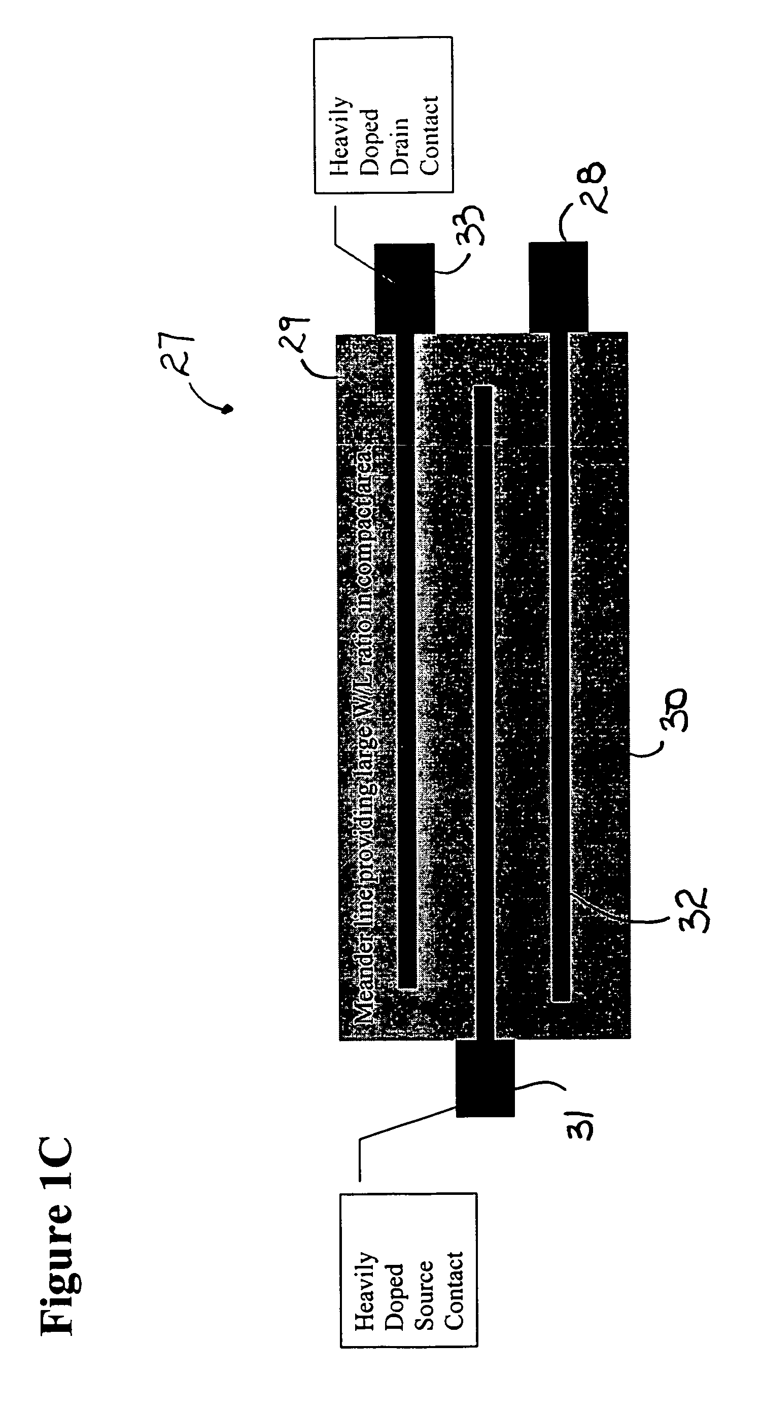
[0055]The method may also include providing relatively large widths of the source, the drain, the conducting channel, the insulator region and the gate region with respect to lengths of the source, the drain, the conducting channel, the insulator region and the gate region between the source and the drain for increasing sensitivity to the target materials.
[0056]The method may also include providing relatively large lengths of the source, the drain, the conducting channel, the insulator region and the gate region with respect to widths of the source, the drain, the conducting channel, the insulator region and the gate region between the source and the drain for increasing sensitivity to the target materials in saturation ranges of the sensing.

Problems solved by technology

There is a significant problem with existing techniques such as electrophoresis and the various blots.
Further, a very large quantity of the tested biochemical is required for electrophoresis detection methodologies.
In many instances the number of molecules available for detection is very small and may be below the sensitivity threshold of the sensor, or may be problematic with respect to sensitivity.
Toxins such as Botulinum toxin are notoriously hard to detect at lethal thresholds because of their very low lethal and sub-lethal, but still dangerous, concentrations.
In the case of c-DNA and RNA sensing, the number of base pairs or nucleotides present may be low creating a problem for adequate detection and identification.
Where only small concentrations of target molecules are available, mass action effects can result in the bound target concentration being very low.
At the very earliest onset of disease, the density of indicative proteins, viruses, antibodies and bacteria may be very low, thus placing a very high sensitivity measurement burden on the sensing approach.
This approach is problematic resulting in drift and small signals.
In the best manufacturing case, such technologies best do not push to nanometer dimensions due to costs, low yields and other adverse features.
Excessive need for signal processing adds costs.
Bleeding of spots can undesirably corrupt specific recognition objectives of adjacent sensors in the array.
Typically, semiconductor based devices show a significant moisture sensitivity leading to erroneous measurements.
Whereas there are methods to provide water protection for Si integrated circuits, these methods necessarily often introduce undesirable features that are undesirable, for example, emersion in a binding epoxy resin.
However, such thin over layers typically do not well protect against water contamination.
Spread over millions of biosensors, this cost saving is substantial.
While such robotic systems can apply multiple chemical mixes to different location on a single chip, the minimum size of the liquid spot is limited.
Bleeding from one sensor to an adjacent sensor can occur if the sensors are sufficiently small and densely arrayed.
Such cross mixing is adverse and can introduce errors of measurement and false positives or false negatives.
For example, substantially sub micron or nano dimensional electrical sensors are generally undesirable for these and other reasons.

Method used


Image

  • Ultrasensitive biosensors
  • Ultrasensitive biosensors
  • Ultrasensitive biosensors

Examples


Embodiment Construction

[0093]A variety of issues are pertinent to making biosensor measurements relating to the attachment of biochemicals and materials. By way of example, such issues include: sensitivity, ease of measurement by non-engineers, instrumentation availability and convenience, and ease of converting measurement information to biochemical attachment, charge and chemical potential information.

[0094]Advantages for circuit and instrumentation use and function, by way of example, include: measurement sensitivity, ease of linking measured data to biochemical quantitative information, ease of measurement, speed, sensor array measurement management, support of automated measurement, support of remote sensing, support of radio linked test reporting, and instrumentation cost.

[0095]Various instrumentation options may be integrated with the biosensors. By way of example, three approaches are provided for illustrative examples that employ specific design approaches. The uses require particular device conf...


PUM

PropertyMeasurementUnit
thickaaaaaaaaaa
thickaaaaaaaaaa
thickaaaaaaaaaa

Abstract

The present invention is a biosensor apparatus that includes a substrate, a source on one side of the substrate, a drain spaced from the source, a conducting channel between the source and the drain, an insulator region, and receptors on a gate region for receiving target material. The receptors are contacted for changing current flow between the source and the drain. The source and the drain are relatively wide compared to length between the source and the drain through the conducting channel.

Description

[0001]This application claims the benefit of U.S. Provisional Application No. 60 / 582,928, filed Jun. 25, 2004, U.S. Provisional Application No. 60 / 582,952, filed Jun. 25, 2004, U.S. Provisional Application No. 60 / 582,959, filed Jun. 25, 2004, and U.S. Provisional Application No. 60 / 582,760, filed Jun. 25, 2004, which are hereby incorporated by reference in their entirety.BACKGROUND OF THE INVENTION[0002]Biosensors have been and are being developed to detect, identify and quantify various biochemicals, ranging from proteins to toxins to RNA to c-DNA to oligos and to disease agents such as viruses, bacteria, spores and Prions. This list is by way of example, and is not intended to be complete. Some biosensors sense charge on the molecule. Many biochemicals carry a net charge. Electrophoresis methods and various blots exploit molecule net charge to affect physical separation of such molecules.[0003]There is a significant problem with existing techniques such as electrophoresis and the ...

Claims


Application Information

Patent Timeline
Patent Type & Authority Patents(United States)
IPC IPC(8): H01L29/772
CPCB82Y10/00B82Y15/00H01L29/0665G01N27/4145H01L29/66439C12Q1/686H01L29/0673H01L29/4908
Inventor HOLM-KENNEDY, JAMES W.
Owner UNIV OF HAWAII
Why Eureka
Try Eureka