Biosensor containing ruthenium, measurement using the same and application thereof
a technology of ruthenium oxide and biosensor, which is applied in the field of biosensors, can solve the problems of sub>, affecting the accuracy of measuring, and not being suitable for cmos standard process materials,
- Summary
- Abstract
- Description
- Claims
- Application Information
AI Technical Summary
Benefits of technology
Problems solved by technology
Method used
Image

Examples
example 1
Preparation of a Ruthenium-Containing Sensing Film and Design of a Measurement System Using the Same
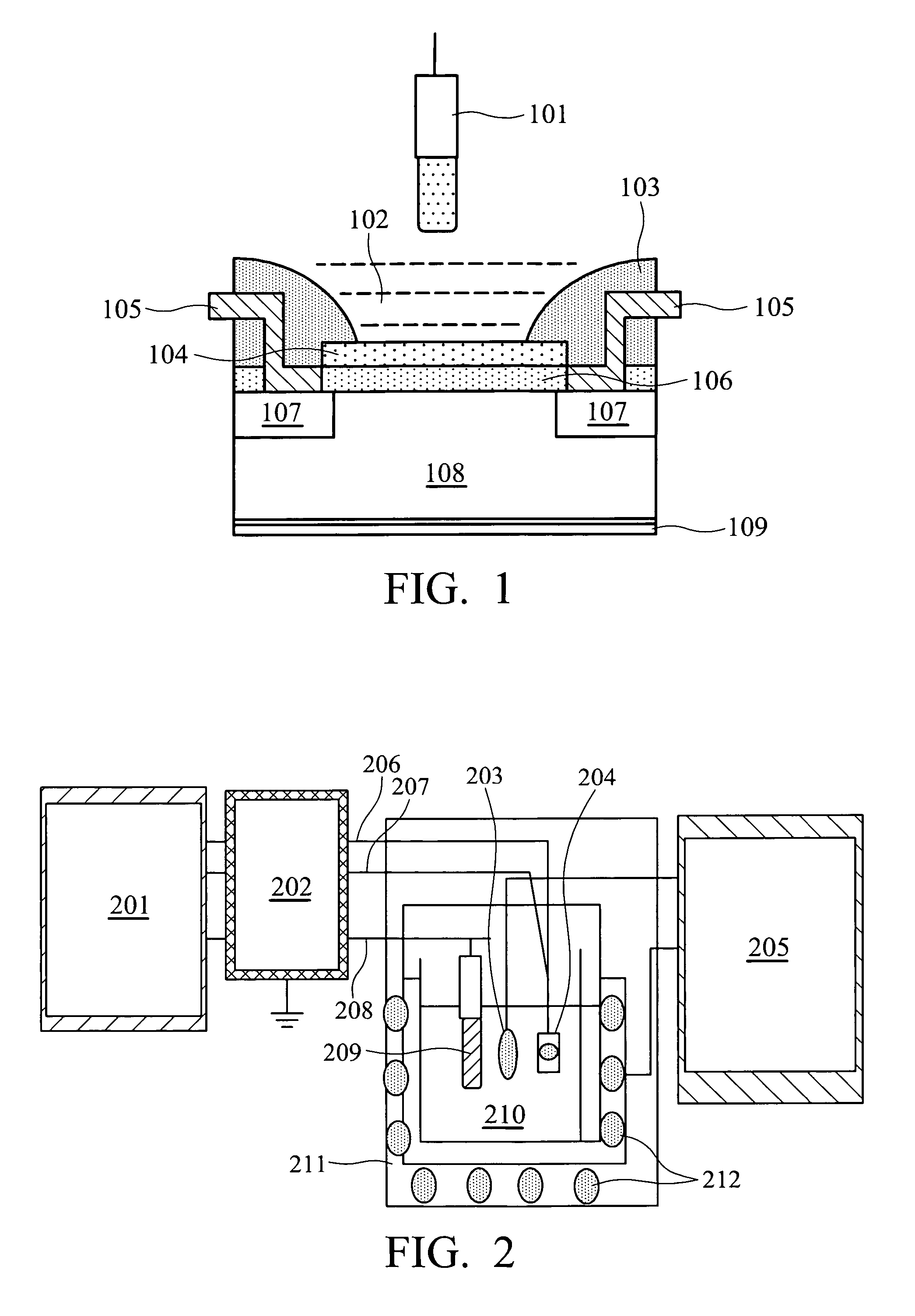
[0103]A silicon substrate was cut to 1 cm×1 cm. The silicon dioxide naturally formed on the surface of the substrate was removed, by immersing the substrate in a hydrofluoric acid (HF) solution with a ratio of HF and deionized water at 1:50 for 10 minutes. The substrate was then washed with deionized water. The substrate was placed in a sputtering chamber. The working pressure of the reaction chamber was maintained at 2×10⁻⁶ torr. For ruthenium oxide film, the flow rate of argon was 40 sccm, and that of oxygen was 10 sccm. Ten minutes pre-sputtering was performed at an initial deposition power of 70 W to remove oxides and contaminants from the surface of the ruthenium target. The deposition power was raised to 100 W for sputtering. During the one-hour sputtering, the pressure was maintained at 10×10−3 torr. The rotation rate was 10 cpm with a rotating holder to ensure even deposition....
example 2
Preliminary Analysis of the Ruthenium-Containing Biosensor
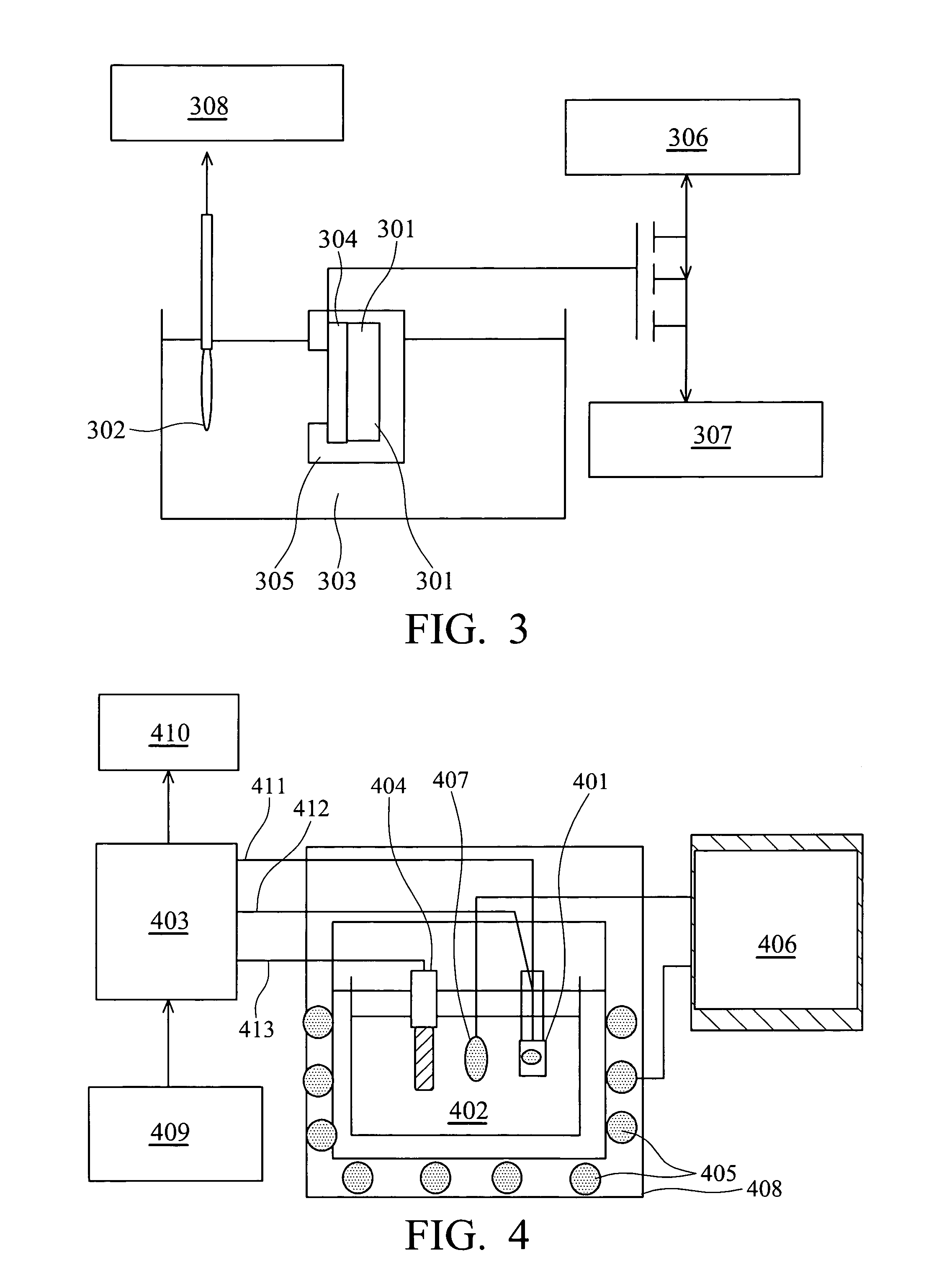
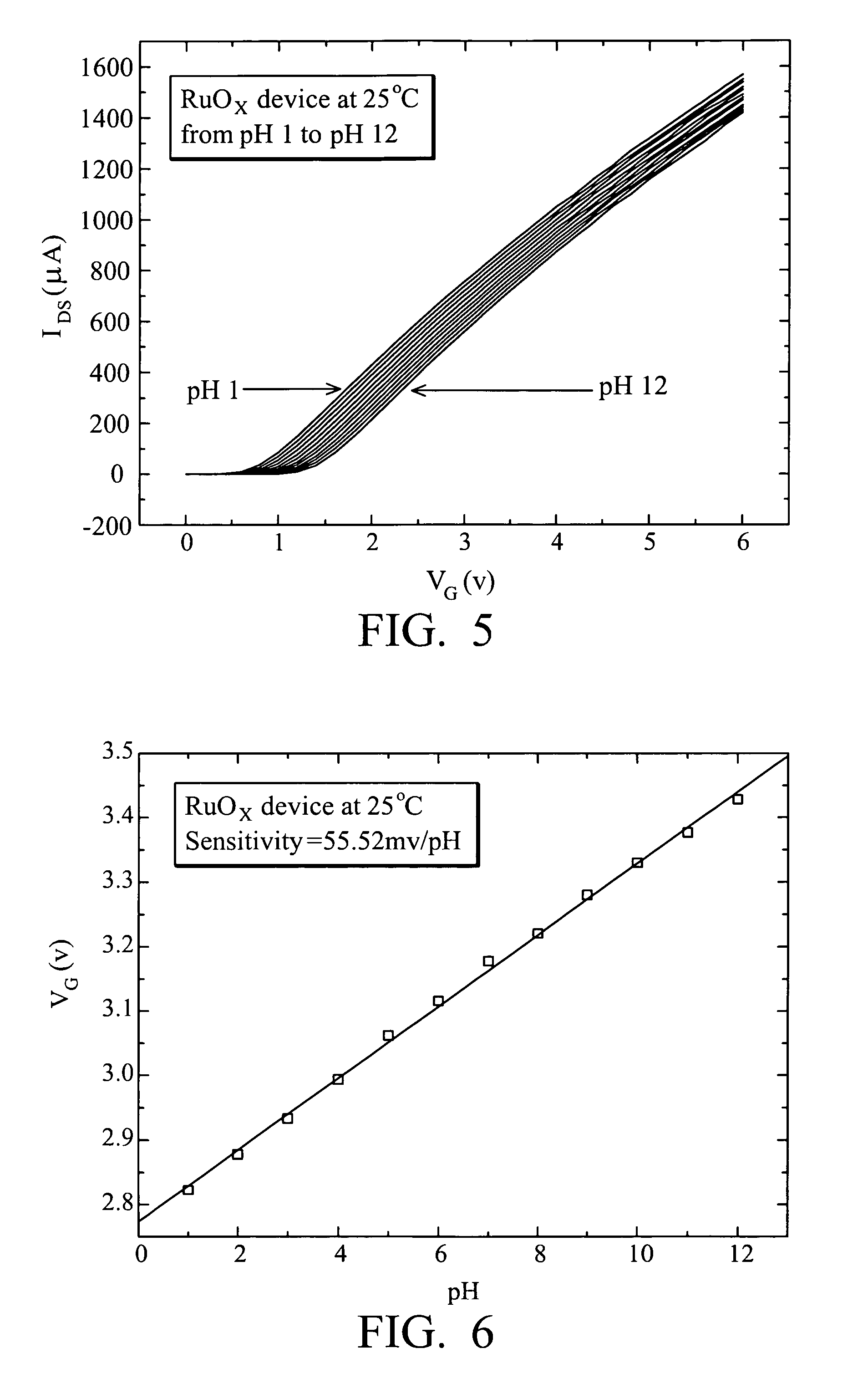
[0108]During sputtering, the optimum condition for the ruthenium oxide or ruthenium nitride film was obtained using the I-V measurement system shown in FIG. 2. The measuring results of the ruthenium oxide film are shown in FIG. 5 and the pH of the ruthenium oxide film ranged from pH 1 to pH 12. The results were converted to the relationship of pH and VG by Origin 6.1 software as shown in FIG. 6, and the sensitivity of the ruthenium oxide film prepared by the optimal sputtering condition was 55.52 mV / pH at 25° C. The I-V measurement results on an enlarged scale showed an ideal linearity with no leakage or noise at the initial voltage. The results of different pH had equidistance, indicating the selectivity to different pH values was good. The measurement results of the ruthenium, nitride film are shown in FIG. 7 with the pH measurement of the ruthenium nitride film ranged from pH 1 to pH 13. The results were converted to the r...
example 3
Characteristic Analysis of the Ruthenium-Containing Biosensor
[0111]To further understand the characteristics of the ruthenium-containing biosensor, the following analysis was performed.
[0112]A. Scanning Electron Microscopy:
[0113]Scanning Electron Microscopy (SEM) JEOL JSM-6330F FESEM was applied for the measurement of the ruthenium oxide film and the results were shown in FIGS. 9˜11. FIGS. 9 and 10 show the front views of the ruthenium oxide film at 50,000× and 100,000× respectively. The crystalline phase and structure of the ruthenium oxide was observed. FIG. 11 is a cross section of the ruthenium oxide film at 20,000× with thickness of 1.76 μm. To determine the relationship between the thickness and the sensing response, a ruthenium oxide film prepared with another sputtering coefficient was formed under working pressure maintained at 2×10⁻⁶ torr, flow rate of argon 40 sccm and oxygen 10 sccm. Ten minutes pre-sputtering was performed at an initial deposition power of 70 W to remov...
PUM
| Property | Measurement | Unit |
|---|---|---|
| response time | aaaaa | aaaaa |
| room temperature | aaaaa | aaaaa |
| Resistance rate | aaaaa | aaaaa |
Abstract
Description
Claims
Application Information
 - R&D
- Intellectual Property
- Life Sciences
- Materials
- Tech Scout
- Unparalleled Data Quality
- Higher Quality Content
- 60% Fewer Hallucinations
Browse by: Latest US Patents, China's latest patents, Technical Efficacy Thesaurus, Application Domain, Technology Topic, Popular Technical Reports.
© 2025 PatSnap. All rights reserved.Legal|Privacy policy|Modern Slavery Act Transparency Statement|Sitemap|About US| Contact US: help@patsnap.com